
Building the PIXELCUBE (Part 1)
I’ve spent the last few weeks on building a cube made out of a bunch of PVC vertices and acrylic edges but with no face, where the edges are filled with over 60 individually addressable LED’s per meter. It’s not done yet, but i felt that sharing an update on why I’m doing this and why it turned out to be harder than i thought would be nice.
Idea & Background
To be honest here, I don’t know how this really started. There is a possibility i was watching something, together with an influx of other ideas that led me to the conclusion that i just had to build a large light fixture. I talked with my friends from Sweden about building something interesting for ANDERSTORPSFESTIVALEN and i guess this is the idea i subconsciously came up with. This is in a way very representative for how my mind works, once it is clear what I want the idea is the result is almost finished inside my head, the end result is clear to me early on but mapping this onto a process of developing is the hard part.
This cube would be a huge physical light fixture that behaved like an LED wall but without the somewhat boring LED wall form factor. If you’ve ever worked with LED walls you know that after a while the 2-dimensional plate tends to become very flat, even if you build intricate shapes with mapping, as light is only projected at a 180 degree angle. There is no volume to it, meaning that perspective is hard to achieve. Since a LED wall maps to a screen, content tend to be 2-dimensional clips, pre-rendered and then applied in a manner to sync to the music. While there is some available software to do generative works, most of this caps out at 60 FPS + has a visible latency due to the processing needed to generate -> feed over HDMI -> go into processor -> get fed to wall.
I wanted to build something that’s different to this, a volumetric cube with the same LED’s that’s in a good LED wall. Having high dynamic range, fast dimming and aggressive driving speed allows for driving speeds over 240 FPS, meaning you’re able to do aggressive PoV (persistence of vision) effects and stroboscopic patterns. All of this while not projecting 2D content onto a 3D fixture, rather building something that’s inherently volumetric
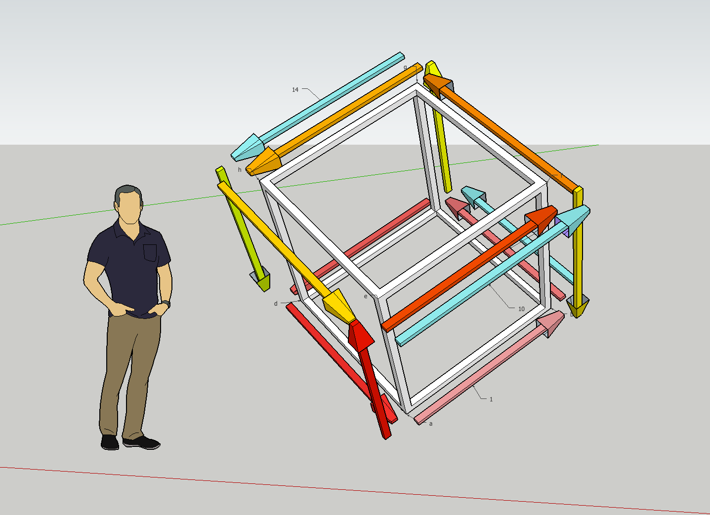
Here’s an early concept around how the cube could look: 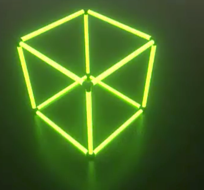
Building this monster
Here’s the thing: I had no idea of how to construct this cube when starting. Absolutely zero knowledge about building something physical except for electronics. So in order to prototype how this would even look, I glued together an old Amazon cardboard box and hanged in my kitchen in order to make it easier to visualize what’s needed in order to build it.
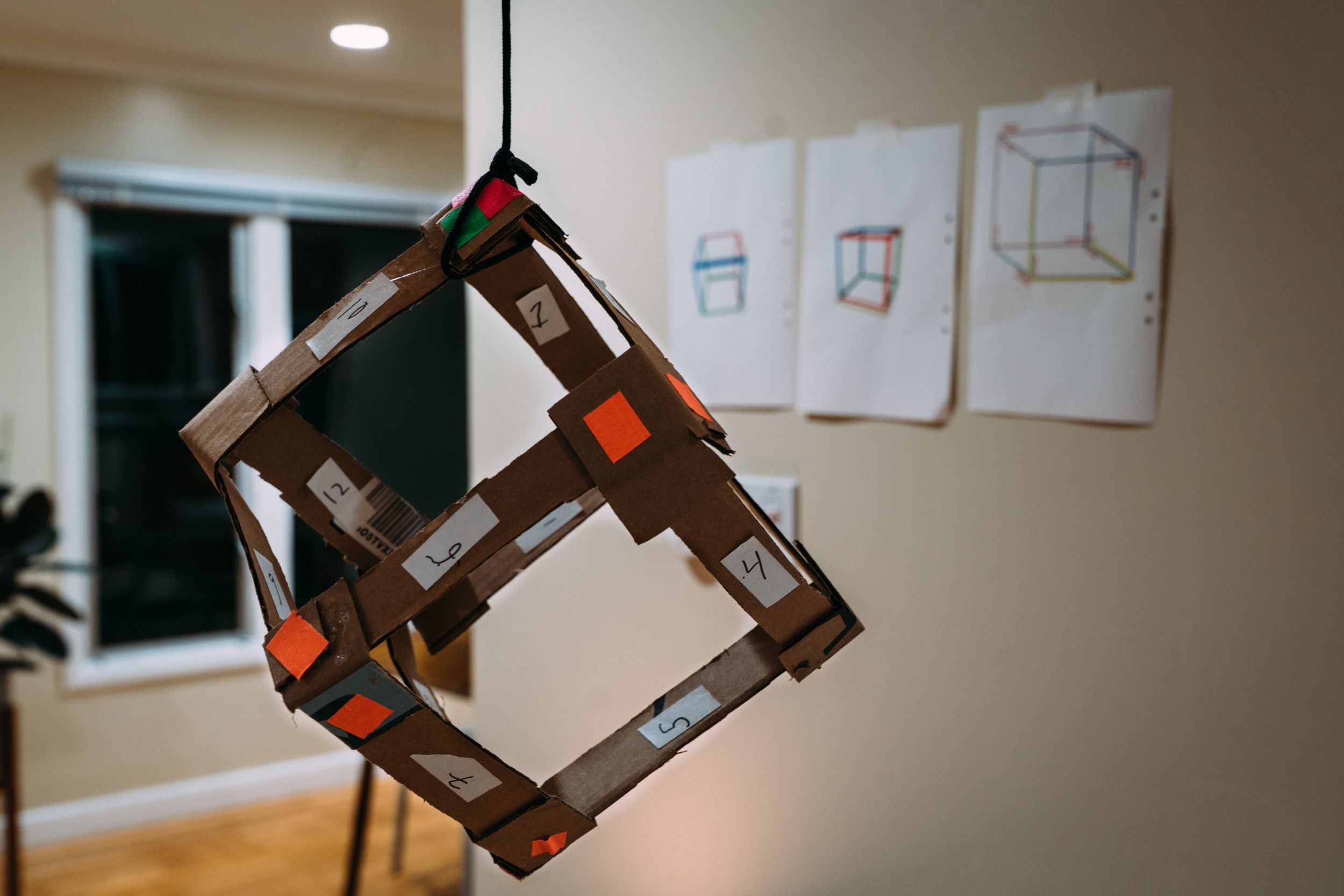
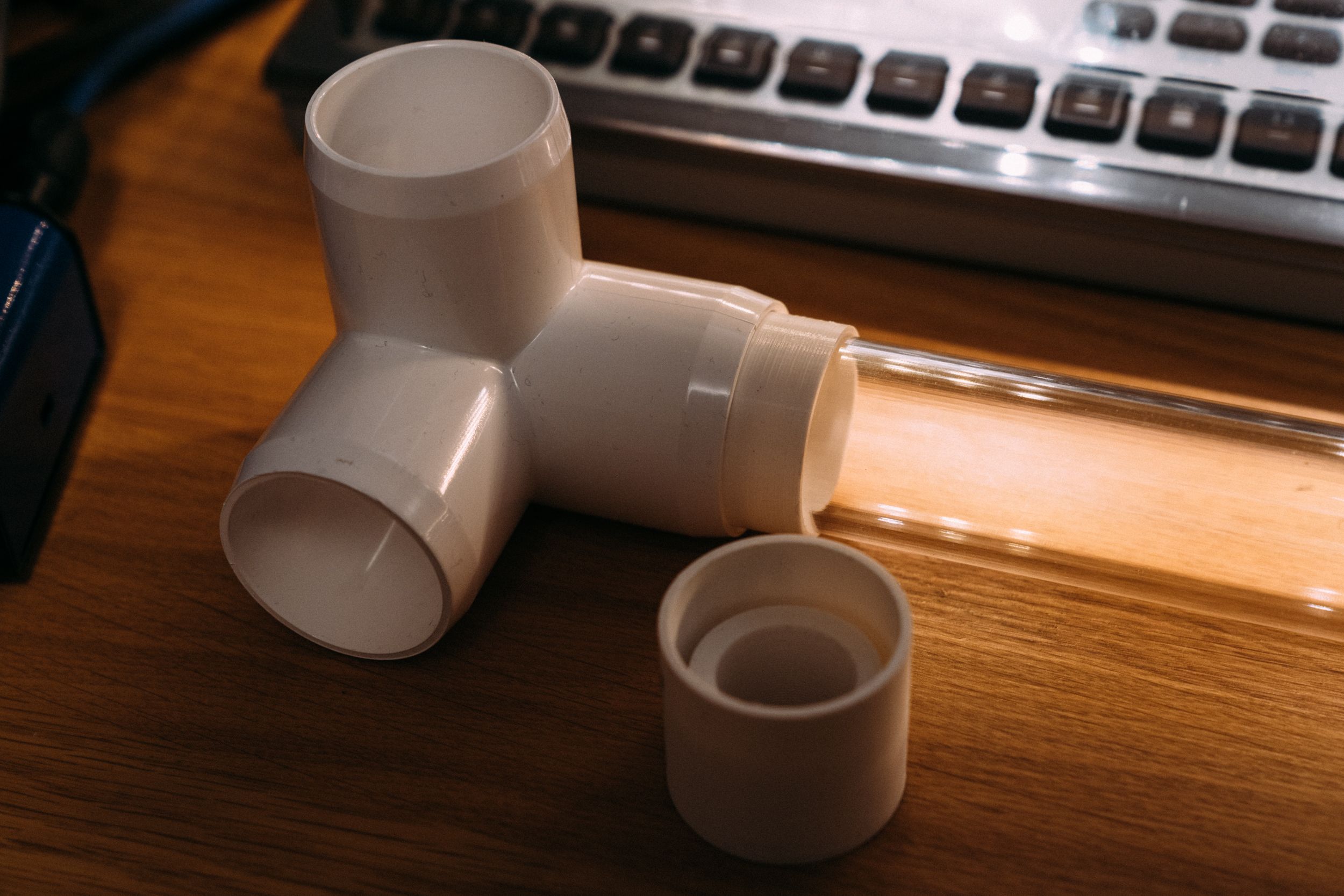
I went through a couple of iterations on building materials and eventually decided to buy the acrylic rods needed and just commit to experimenting instead of trying to solve this on paper. After a long internal debate, i ended up deciding the cube would be 50 inches per side (+ some for the fittings), since 50 inches is exactly 127 cm (very pleasing). I ordered the acrylic rods and once they arrived i immediately realized i had a couple of issues.
Turns out that these acrylic tubes are measured in outside diameter, whereas PVC pipe fittings are measured in inside diameter with a standard thickness, meaning my 1/2 rods had no great counterpart. I ended up trying to solve this problem for a fairly long time, trying different approaches with heat shrink tubing, electrical tape and some other experiments in order to adapt them with no good solution.
No idea of how to make the LED strip “float” inside the acrylic tube. I thought i could mount it on a L angle aluminium bar, but how would i fixate the bar with such tight clearances inside the fittings?
No good way of actually fixating the rods inside the fittings. Since the cube is to be suspended at 45/45 degrees rotation, it needs to have a strong rigidity in the edges, something that friction alone can’t provide. I experimented with a bunch of different solutions to this problem with no really good outcome.
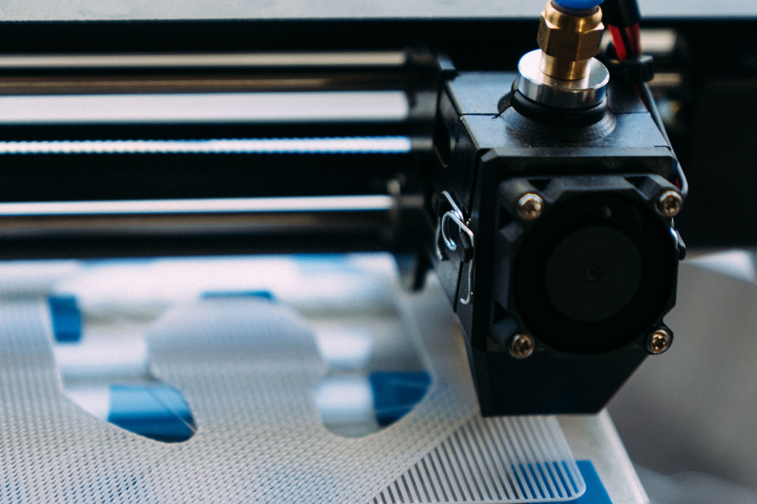
With all these problem stacking up i started to get a bit negative about this project. It was hard to solve, at least if i wanted it to be close to what i imagined it and not take shortcuts in regards to the build quality. I did not want to have multiple support wires inside the cube and I could not find a good way of actually mounting it. In times like these it turns out that an outside perspective is key. I had two good friends visiting (Love & Pajlada) and they came over to my house in order to hang out and look at the cube. Something Love immediately suggested is that i should 3D print the parts i needed, both to hold the fittings and to hold the L angle. I knew basically nothing about 3D printing except from a small part that I sent away for 3D print on a previous project. This did not stop me however, i purchased a Monoprice MP Select Mini 3D Printer V2 and started printing some test parts I modelled. Turns out this is exactly what i needed.
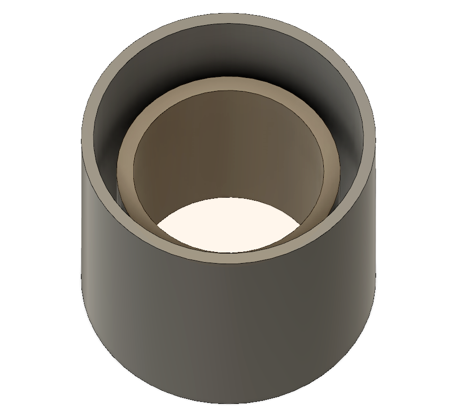
This just shows how important it is to have an outside perspective when getting stuck in projects. Having Love vet my ideas and add his perspective basically made this project possible. It’s a possibility that i would have come to this conclusion eventually but never as fast as i did here. The fittings are now tight and I’ve modelled in holders for bolts so i can use it as a mounting plate for the screws. On top of this the parts also hold the L angle which has the LED strip mounted on it.
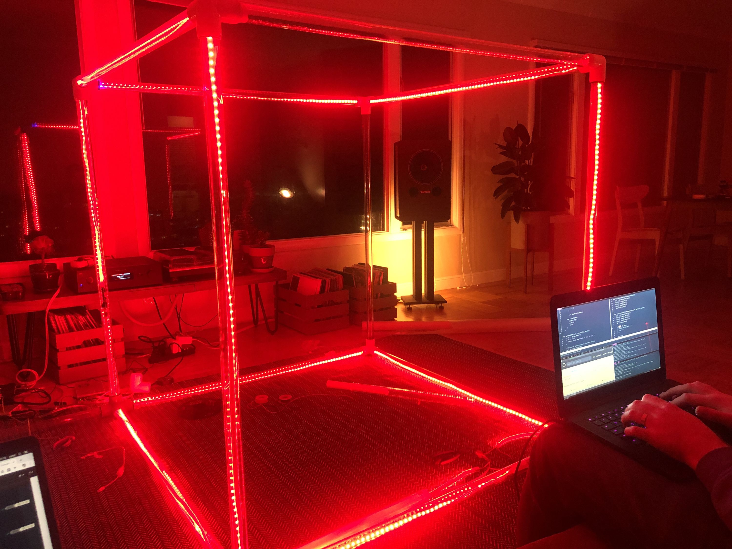
After experimenting together over the weekend, we put together the cube temporarily, just feeding the strips through the rods and taping it with electrical tape in order to hold it’s form. After the first power-up it was obvious that this was i was striving after from the start:
LED & Processing hardware
The vision puts a couple of different requirements in place, namely a driver that can generate patterns at 240 FPS and do music analysis and a LED strip that’s powerful enough to deliver on this. With these restrictions in place, i had to start looking into what could be used to build this piece. For LED’s it turned out to be rather obvious, the chip / strip that has what i need is the APA102, also referred to as the “superled”. The APA102 has a lot of features in contrast to the WS2812 with the primary one being a separate Data / Clock line, meaning the timing of the data is less sensitive. You also get a much higher dimming frequency + a global intensity allowing for LUT lookup to get a higher dynamic range. There’s really no negative part about this LED except for the price.
In order to drive these LED’s i need a platform that’s fast enough to do super granular FFT analysis, has audio input, networking on-board and preferably some groundwork already done. There’s a bunch of directions that could be taken here:
-
Since i wanted this to be a no hassle setup, the TouchDesigner setup goes away immediately. On top of this, TouchDesigner has a node based layout and for some reason this never plays well with my way of thinking. I’ve tried these node based UI’s multiple times and never felt that they’ve been powerful compared to just writing it.
-
An Arduino is just too slow.
-
Raspberry Pi is what i ended up prototyping all this on. It’s a great device but sadly it just doesn’t hold up when you start trying to push multiple volumetric patterns at 200 FPS.
-
PixelBlaze is a great alternative. Ben Hecke has built a very neat small controller on the ESP8266 platform (with a ESP32 upgrade in the works) that’s the easiest to setup and get started with. It basically runs itself however i felt a tad limited by the CPU speed and general pattern blending. It was hard to re-use components of patterns or mix multiple patterns.
-
The SnickerDoodle is a good alternative but coding FPGA is a nightmare. On top of this the actual ARM core isn’t that fast, it runs a 866 MHz Dual-Core ARM Cortex-A9 which is slower than the Raspberry Pi so a lot of functionality would have to be shifted to the FPGA, even more headache. It’s also not really rapid prototyping working with FPGA’s. I have one of these sitting around but this is a “in case of emergency” solution.
With all this considered, this is the actual solution:
Intel NUC with a FT232H chip attached
This is the route that I will end up taking with the finished cube. It gives me enough CPU speed in a small package, less of a headache in terms of setup and can be mounted inside enclosures. The FT232H chip speaks SPI at up to 30MHz, which is perfect since i only need 20. However, this requires me to write most of the software to drive it.
Wiring and electrical
How does this cube even get powered? After looking at the datasheet of the LED’s it turns out they can pull up to 50mA per LED. With 75 LED’s per rod and 12 rods, that’s about 900 LED’s to drive at 5V, not exactly something you can do with a regular USB port.
The PSU to drive this needs to be at minimum 45A at 5V in order to drive the LED’s at peak load. Mean Well has exactly what i need. These PSU’s are commonly sighted within LED walls so I felt safe with this option. Still, pushing 45A at 5V requires a thicker cable, since the drop over distance will be substantial. Now this is a question of how the cube gets wired, since the APA102 LED’s also needs to be connected in sequence. In order to figure this out, i drew it out in Sketchup in order to visualize the connection order. Once i drew it i realized this is common graph theory issue, how can you walk all the edges in the shortest amount of trips. (entry -> a - ab - bc - cd - da - ae - ef - fg - gh - he - ef (through skip) - fb - bc (through skip) - cg - gh (through skip) - hd )
When building the rods I add an extra signal wire and 5V carrier on the back side of the L angle, that way i can create a common voltage rail for the 5V stuff and have backfeed for signal in order to wire it up as seen in the Sketchup.

In order to connect all this, i’ll use regular Molex connectors in the ends with a custom split one for 5V and serial ones for data in order to wire it all.
Software & Design philosophy
So as mentioned in the beginning of this post, in order to break free from the 2D video mapped onto 3D textures, the cube has to support volumetric patterns. Think of volumetric patterns as resolving pixels inside an XYZ space, you could for example use a 3D model have the intersecting LED’s light up on start. The software should be able to seamlessly mix between patterns and needs input from multiple sources, such as Websocket, OSC, Audio and Time. After discussing the structure with Love & Pajlada, the processing pipeline ended up looking like this:
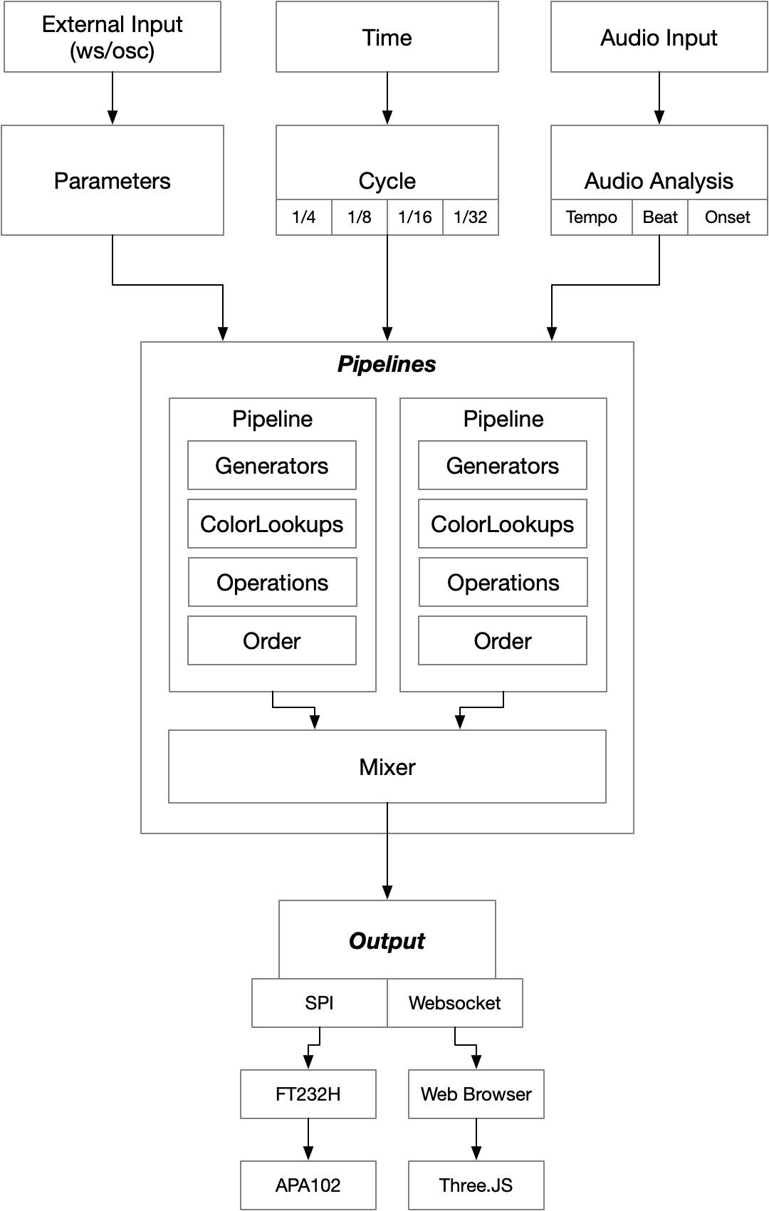
This is the layout of the intended processing pipeline. The pipeline is almost like a node based editor, in the sense that it uses multiple generators producing floats for every single pixel between 0.0 and 1.0, the operators you chain together with various operations is what creates the effect. You could for example use a stroboscope effect, chain it to a colorlookup that changes the RGB output to red and in that way create a red strobe, a hue shift or colorizer becomes powerful especially when using pre-defined palettes. The generator & color lookup can also make use of the FFT data and the beat in order to generate dynamic, music-driven effects with high resolution.
It helps to start with the layout of the flow, since it makes it easy to figure out what software has to be written and what tools to use. In this case i decided on Go for a couple of different reasons.
I know Go. Use what you know, the intent here is not to build distributed software, but to make this cube look good.
Go has great SPI support. Go supports the SPI chip on the Raspberry Pi, the FT232H chip and the APA102 led through periph.io. This makes it easy to prototype and move between different hardware stacks. I can do the prototyping on the Raspberry Pi, developing on my Mac and effortlessly move this to a Intel based Linux box without having to deal with compiling for different archs.
Go is fast enough. Compared to Node.JS and the other languages i evaluated, Go hits the sweet spot between rapid iteration and execution speed, which is needed for achieving a solid 200 FPS.
There are bindings for aubio and PortAudio. Getting audio in and performing analysis on it turns out to be very easy with good bindings available for these two great libraries. Aubio itself provides you with tools to analyze and make sense out of a PCM audio stream, detecting interesting data like tempo, onset, beat and loudness. On top of that you also get a good FFT implementation. PortAudio makes it easy to acquire audio across all platforms, lending into the goal of portability between platforms.
Timeline
I’ve been working on this since late October and intend to finish this before June 30th 2019 in order to bring it to ANDERSTORPSFESTIVALEN. As you can see, at the time of writing this post the cube is not yet done. I will post updates here on the blog once more progress has been made. I will end this post with a video that I shot when we tested the cube: