
Printing & Crimping (Pixelcube Part 3)
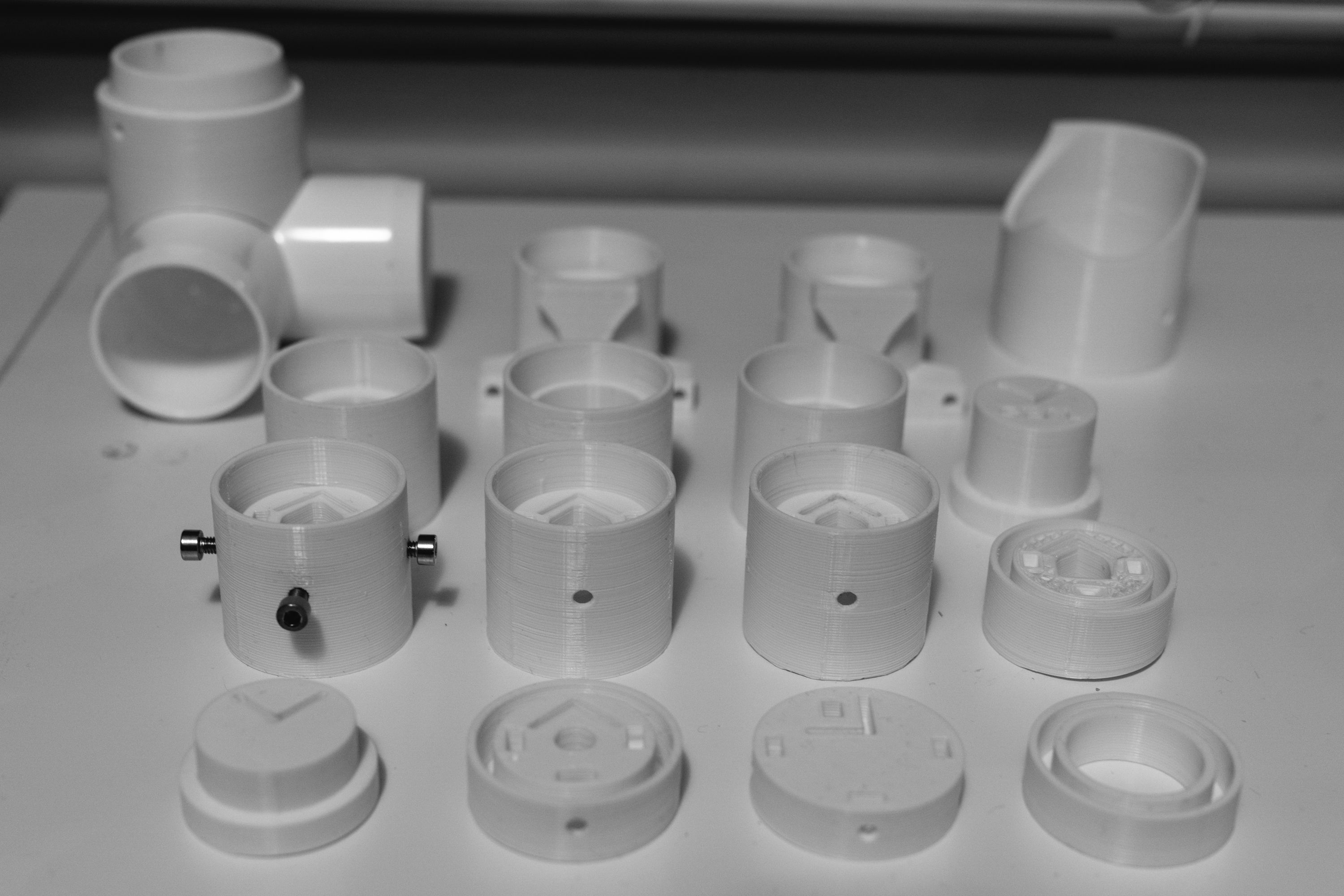
The last two weeks has mostly been a repetitive process of sketching in Fusion360, slicing, printing, verifying and realizing i need to tweak something. Hence repeating this entire process over for a couple of iterations. Since the tolerances of the fittings needs to be perfect, the whole thing becomes an interplay between designing around the limitations and tolerances of the 3D printer while having the parts come out as i want them. All these iterations has become quite a few prototypes:
This is also the reason i decided to make the lamp in part 2 as a different project. There was a lot of prototyping i needed to do to verify that the approach is sane, building a lamp allowed me to verify some of these ideas without printing parts that i intended to throw away afterwards. Sort of like a stepping stone in order to reach the final decision.
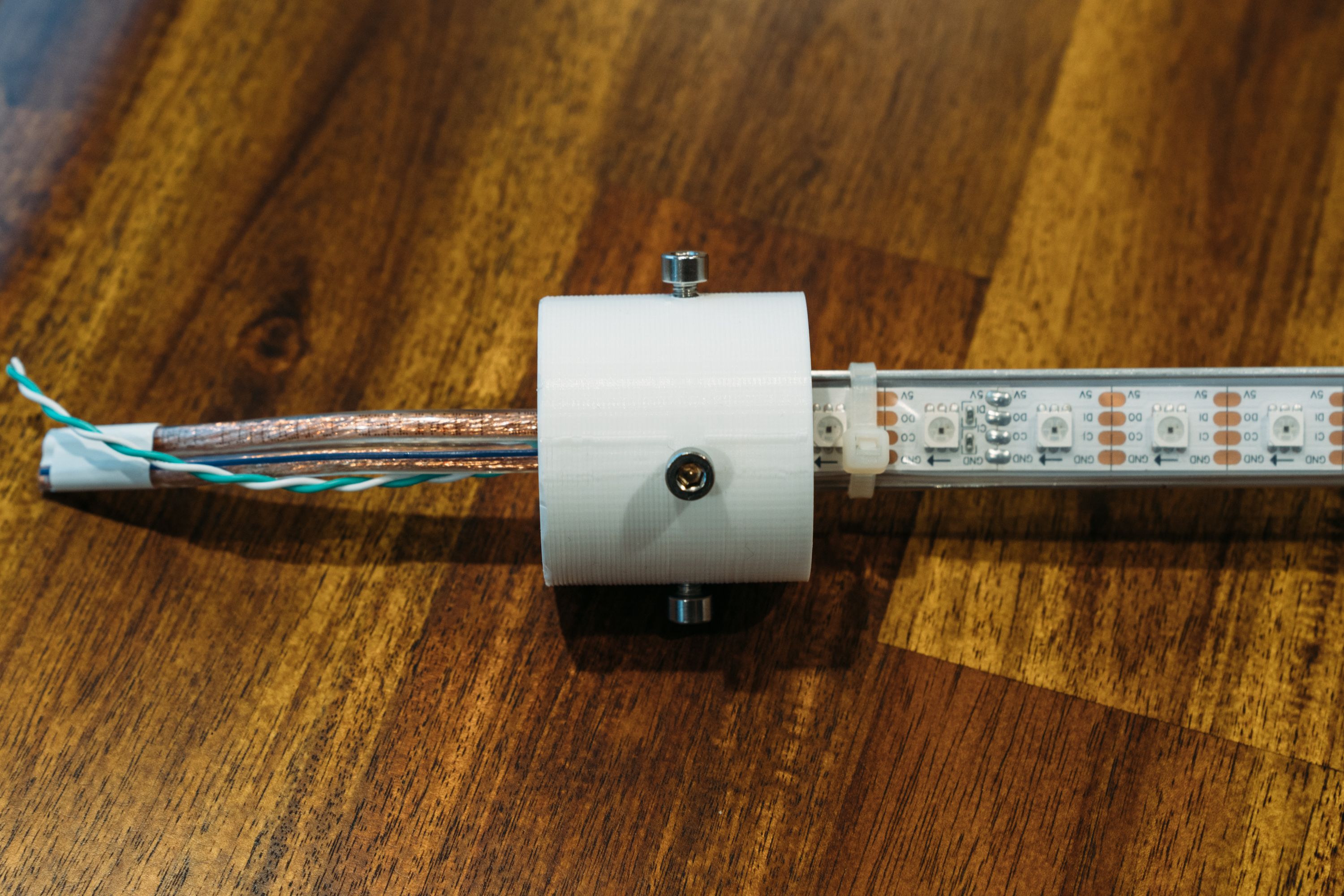
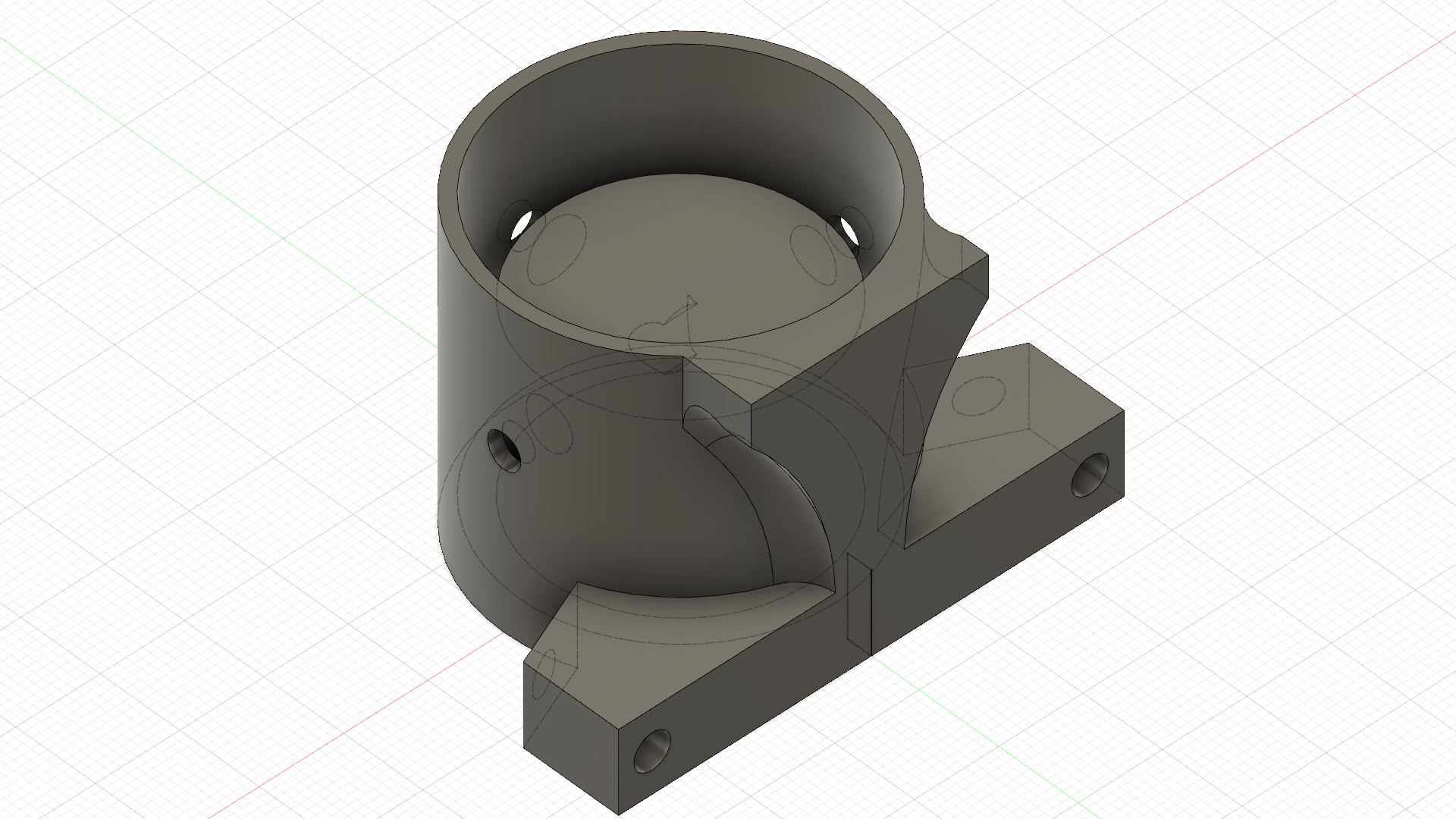
After designing quite a few different variations on the end caps for the rods i settled on a design where three M4 hex nuts can be slotted in, locking the rod in place through pre-drilled holes while holding the L angle in place through a slide-in fit.
With this done (a relief) i had two remaining problems:
- Deciding on how the rods connect to each other
- How would i drill exact holes on the 3 way fitting & on the rod while keeping it secured?
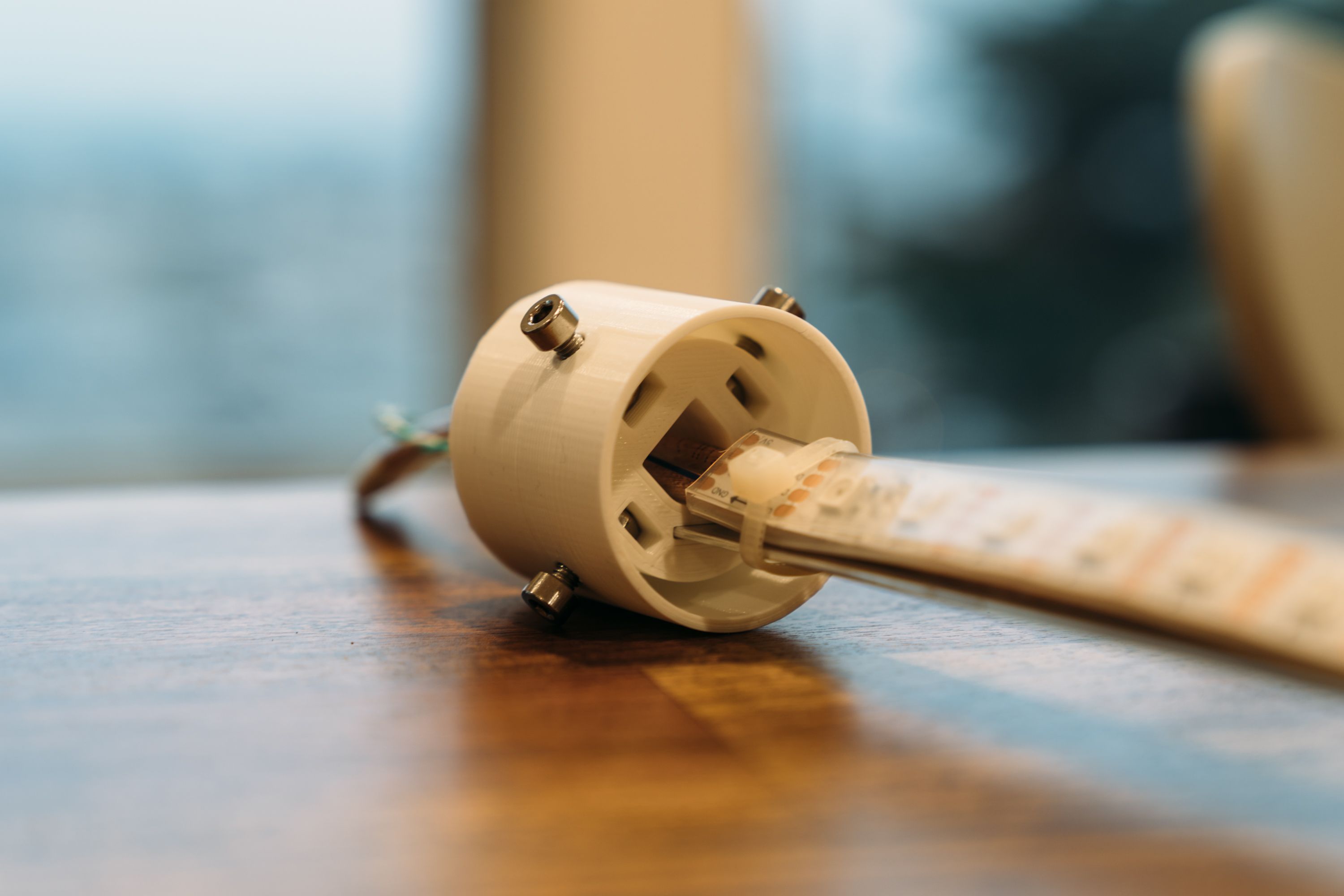
After looking into a bunch of options on different connectors and solutions it was clear that there had to be an actual connector, a terminal block would not work due to the restricted space within the fittings. Since the budget had already gone out of the window for this project, going for Molex Connectors seemed to be the right choice. I purchased a bunch of Molex SL and Molex 0.93 2 pin connectors from Mouser, with the problem being that Molex has maybe a million different connectors, so figuring out what exact connectors to use was hard. For example, this is the spec for a Molex pin, figuring out what goes with this is not obvious if you haven’t used the ecosystem before. Someone should build a digital Molex compatibility guide. The Molex SL connectors are perfect for the SPI and the 0.93 plug can sustain up to 15A, making it perfect for the use case. You also have to buy the for some reason ultra expensive Molex tools (sad face).
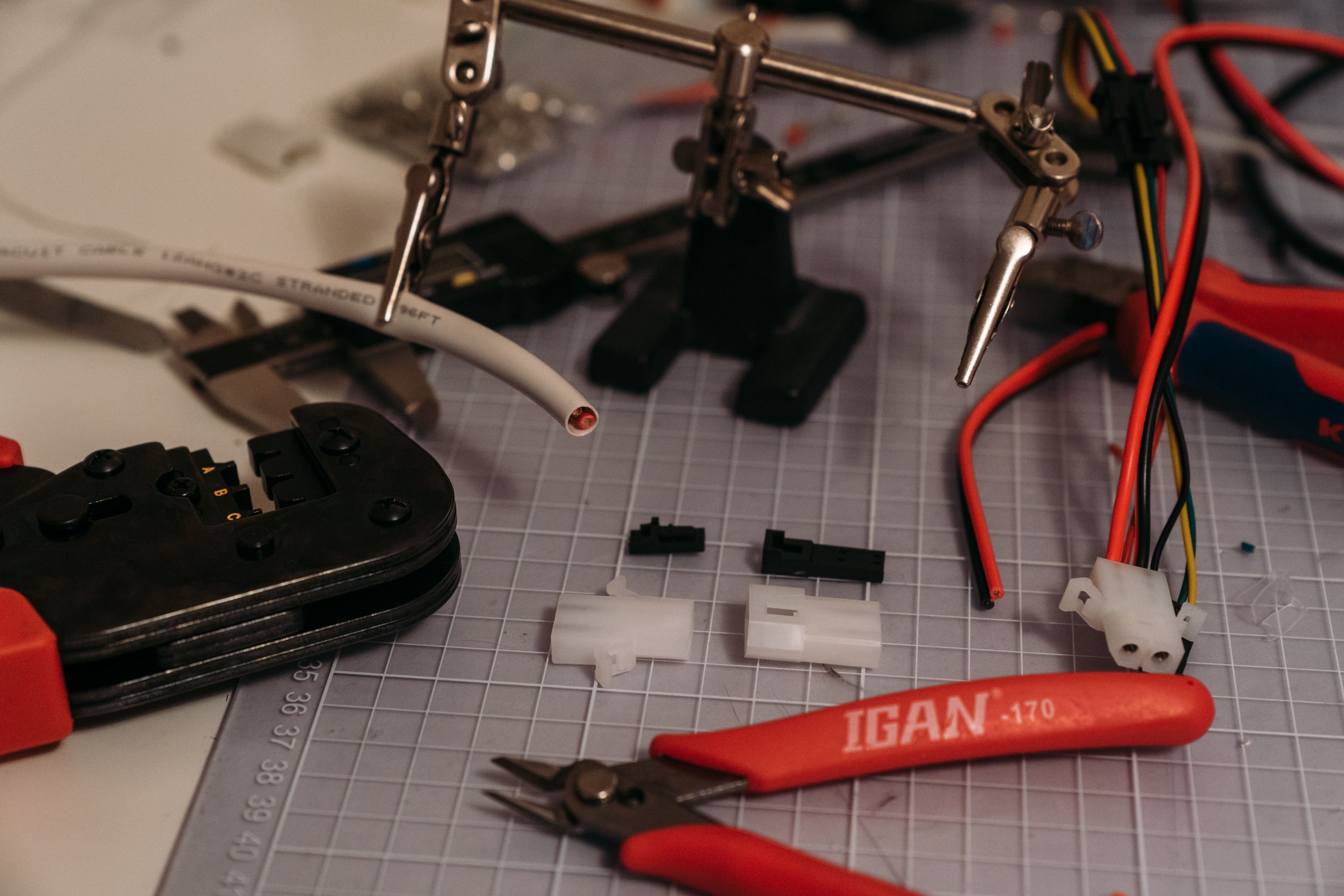
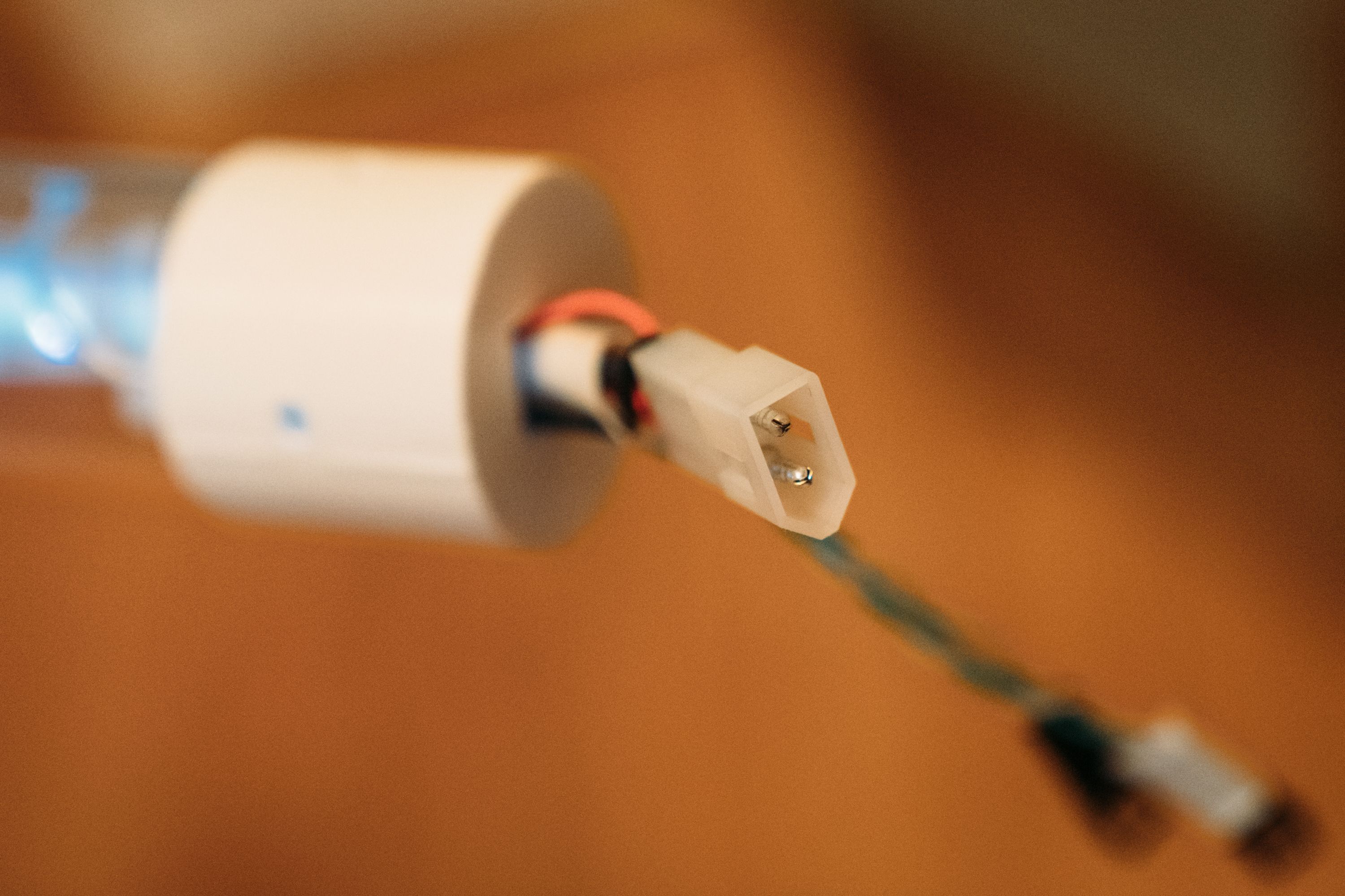
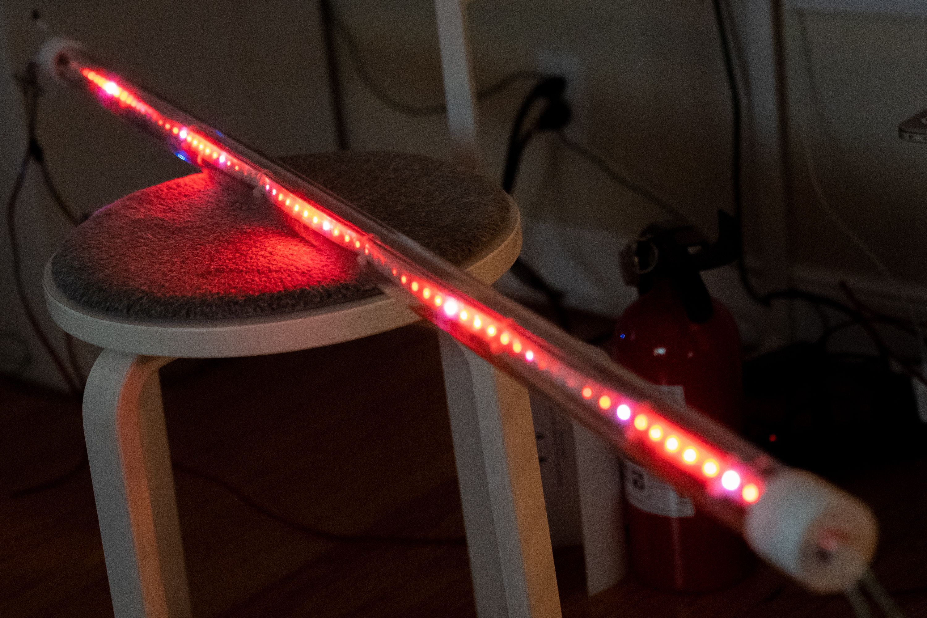
With all this done, a rod could finally be powered up in the form it will have when this cube is done, using the proper connectors and a simulator to drive the APA102
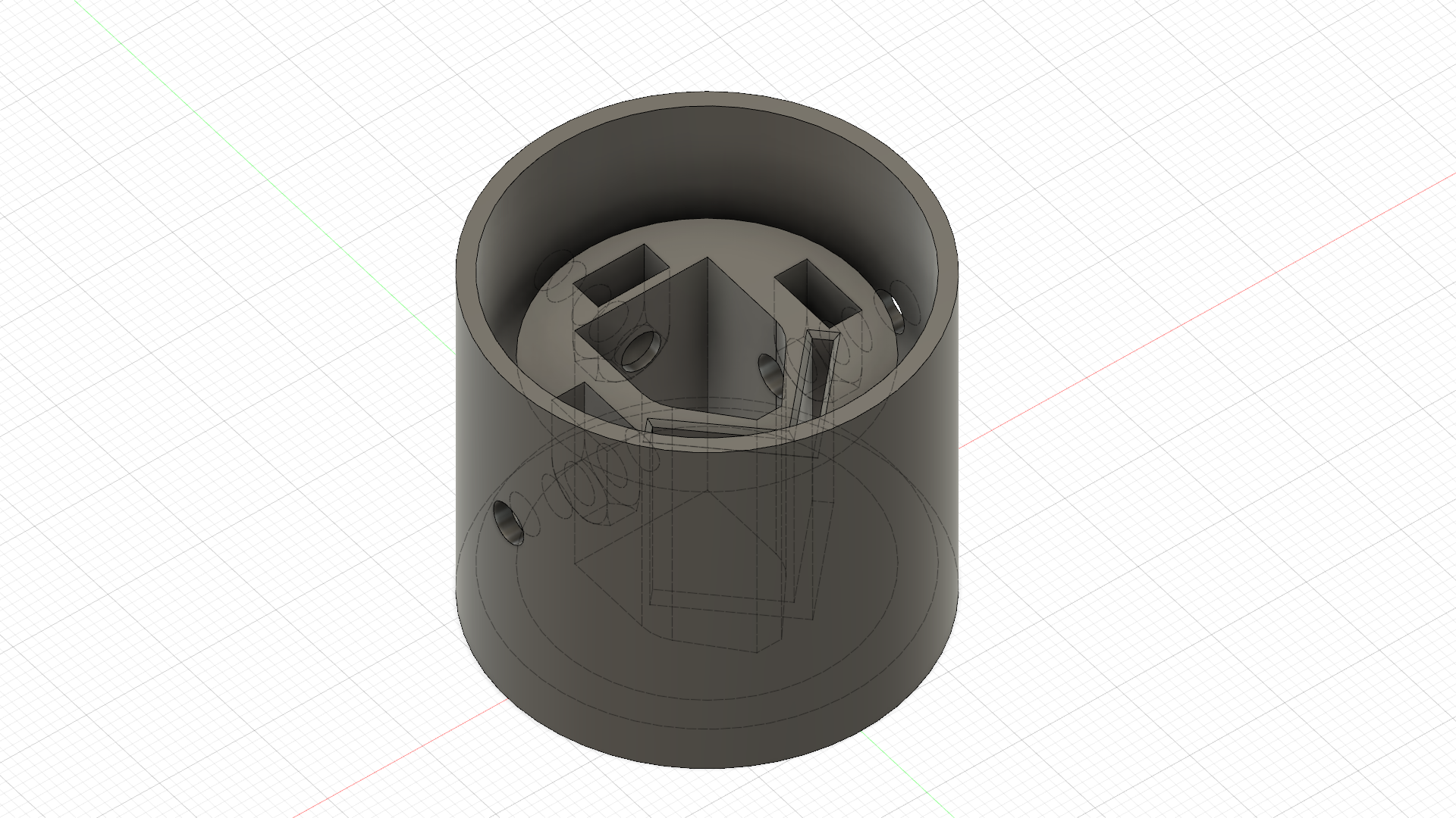
So for the second problem, this was again one of the situations where Love had great feedback on how to approach the problems: “Just 3D print a fitting for the fitting with pre-printed drill holes 4Head”. Sounded like a wild idea but had to try at least, so i designed a hood for the 3-way PVC fittings:
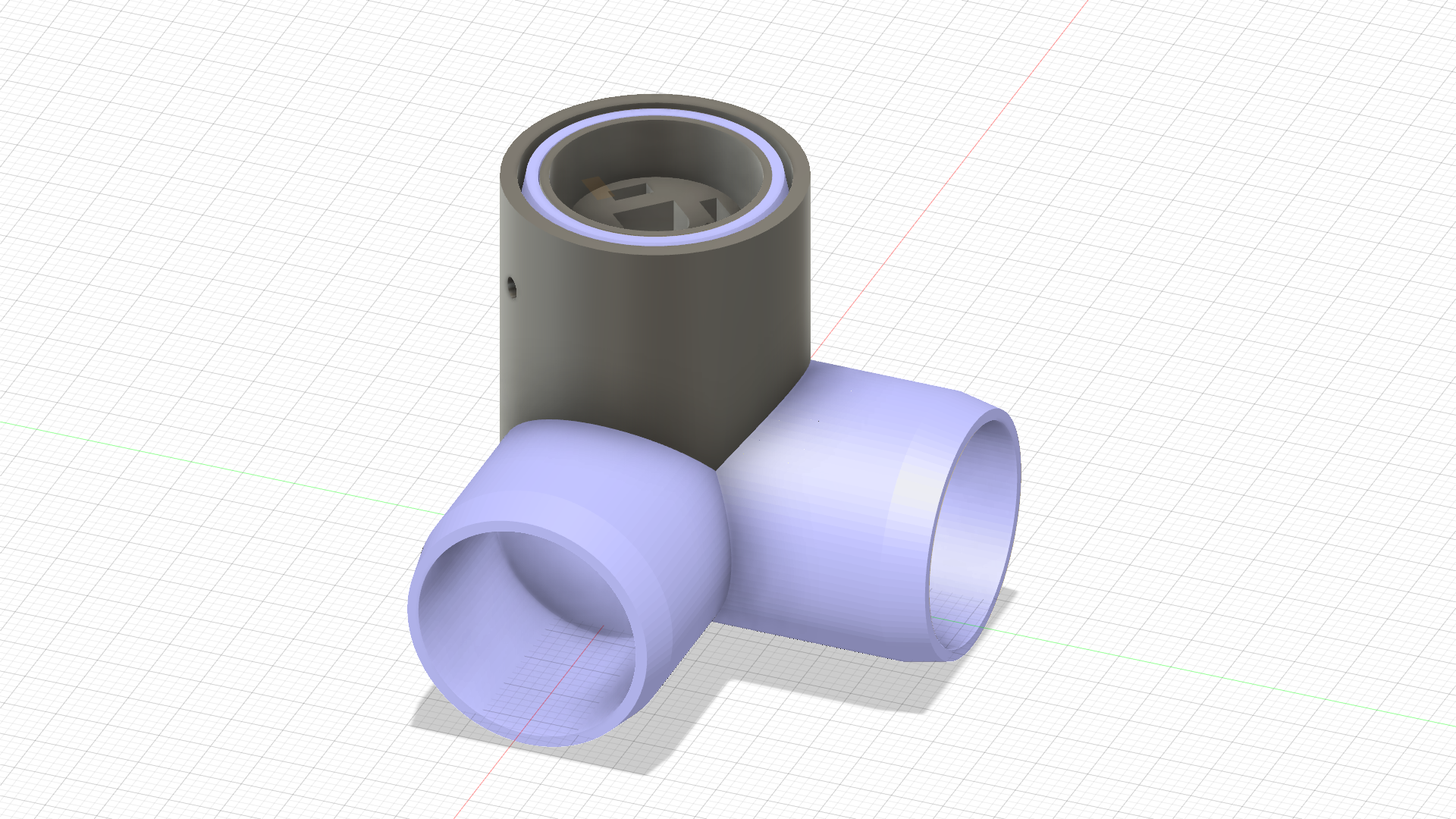
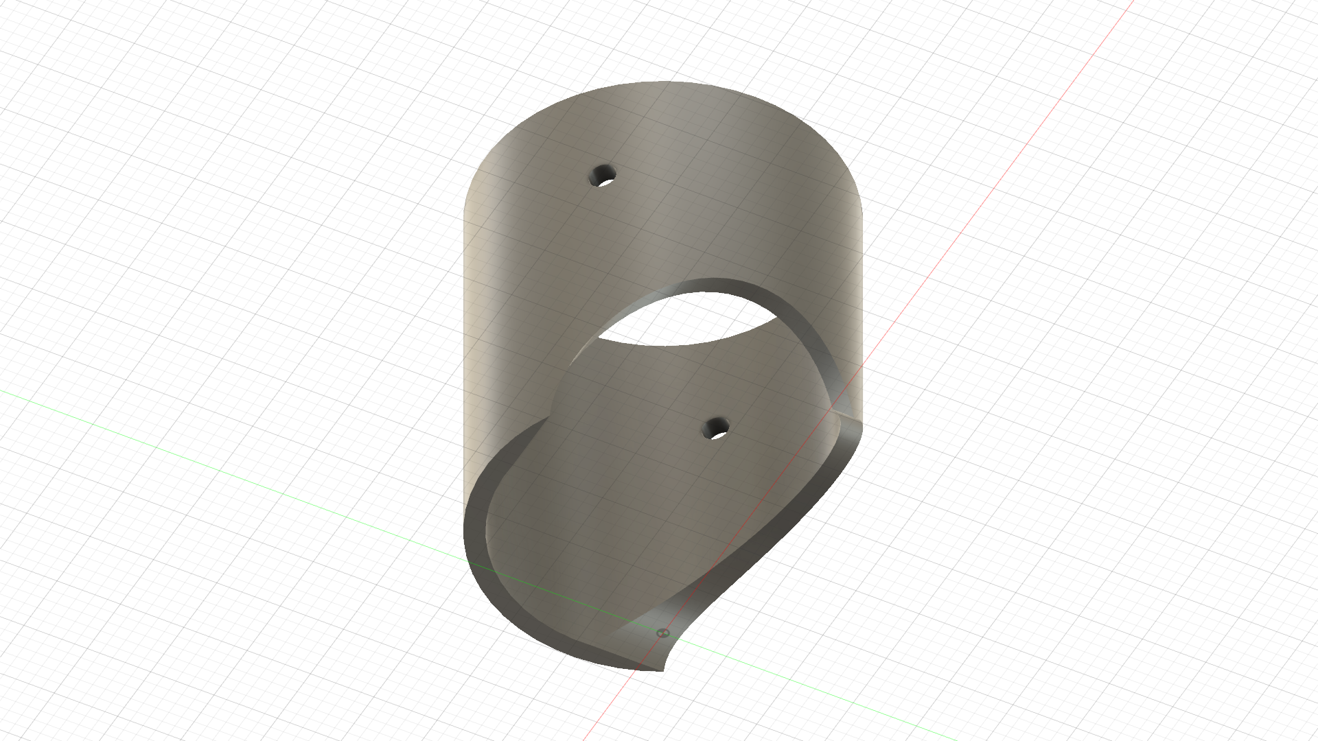
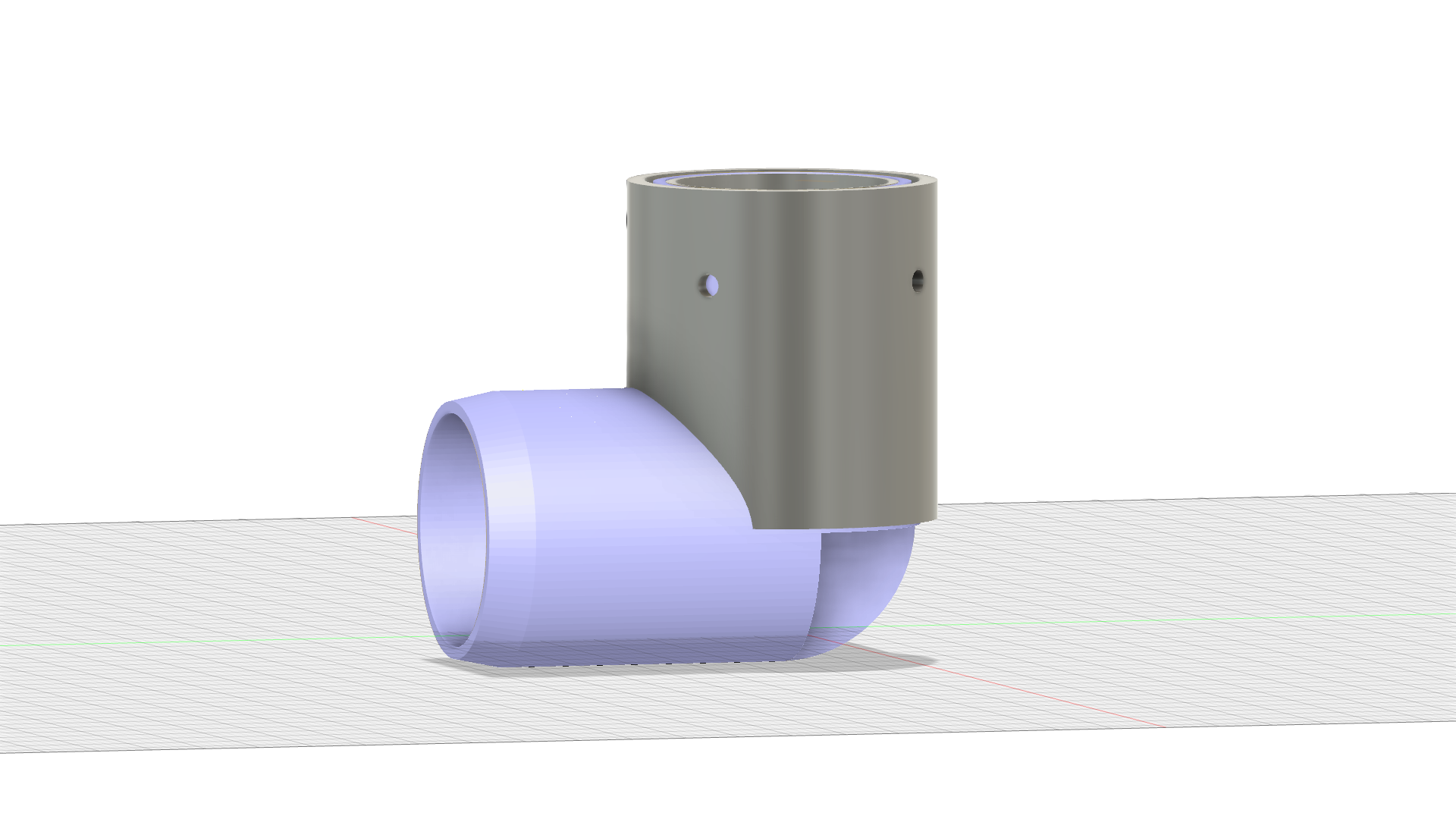
Printing this turned out to work also (after some tweaking of the model). Sliding this on onto the 3 way fitting ensures a snug fit while making it easy to drill perfectly aligned holes. I ended up sketching out the same approach for the rods, with two symmetrical drill mounters that i can screw to a table with a rod mounted and use as a drill guide.
With all this done, the remaining parts for the building of the cube is actually just manufacturing 11 more rods, which due to the printing time (9 hours per rod) will take a fair amount of time on the smaller 3D printer i have. Thanks to this though i can head back onto writing the software. Software wise I’ve changed my mind about some minor design implementations but this is something i will cover in the next blog post.
Hope you enjoyed this update, I will try to post the next update within a few weeks!