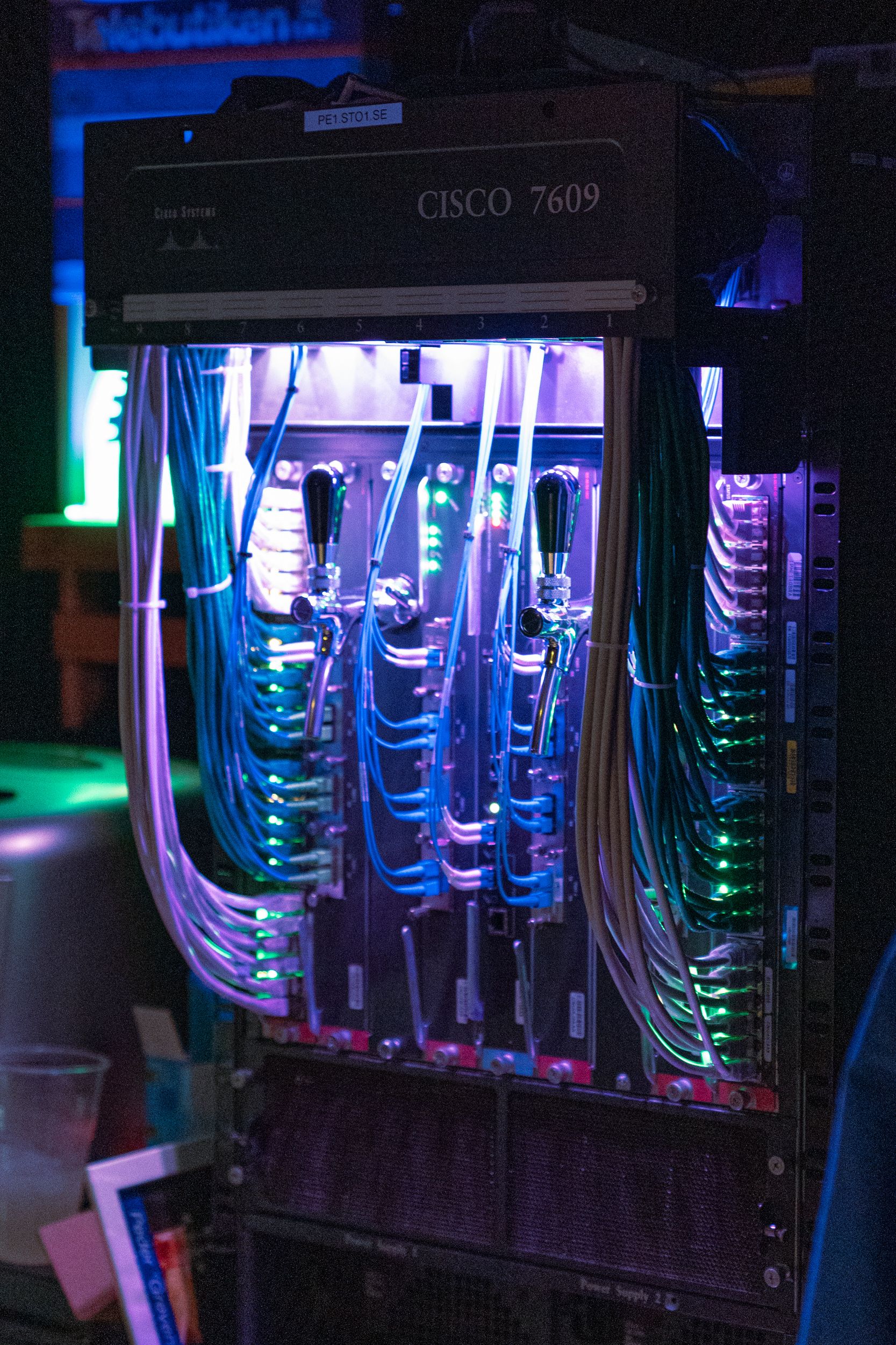
Converting a Cisco 7609 into a beer tap
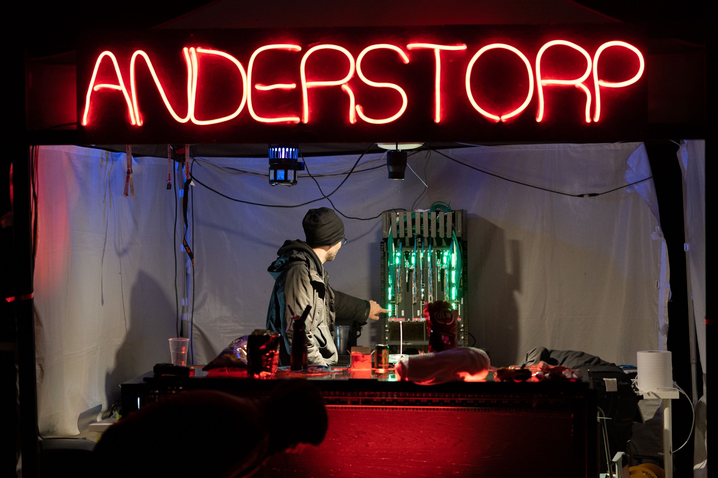
Last year I thought that we had reached some sort of peak in terms of how far one can go in building useless things by converting a 42U rack into a bar. Shortly after that the people that built the bar visited San Francisco and we started thinking about what the next project could be. After a good amount of alcohol we discussed memories and I started thinking back to the “Tech PoP” at DreamHack. You see, at DreamHack, the network volunteer crew used to have a couple of racks that they setup for display showcasing the routers that powered the network, a marketing ploy which was cool in 2006 when the bandwidth that DreamHack used actually mattered. Fast forward to 2015 and the network crew started filling the racks with useless hardware just to make it look cool, there was even a big NAS connected that served no purpose other than stroking the egos of the people that volunteered in the tech crew.
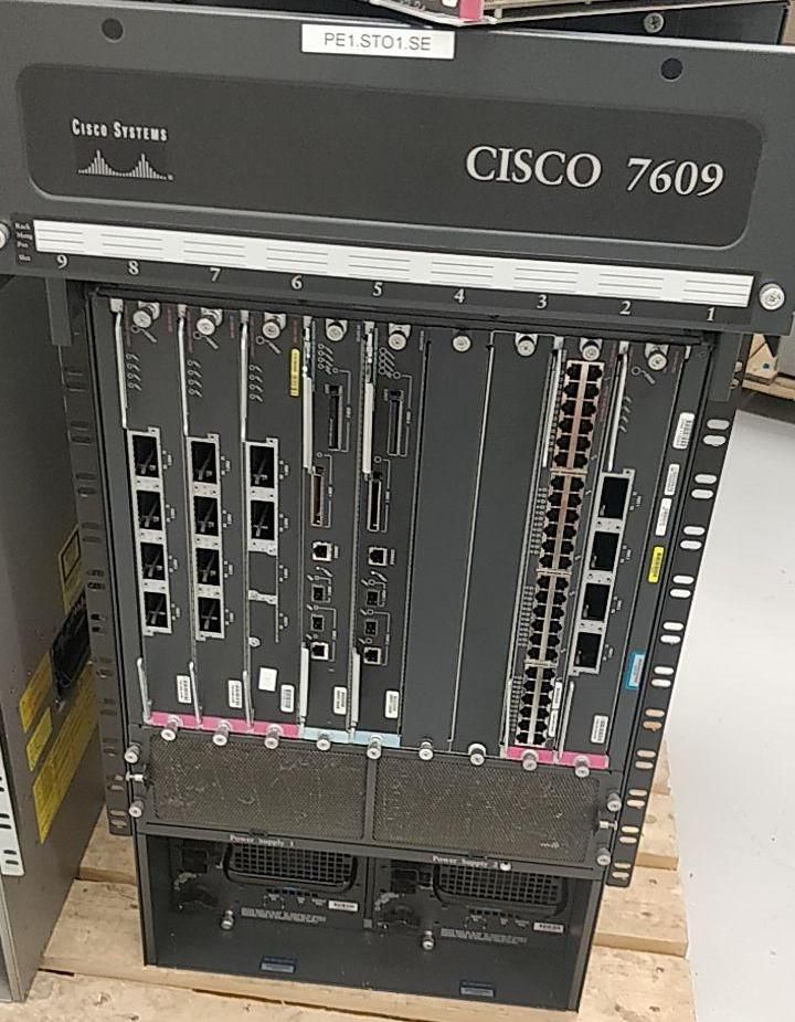
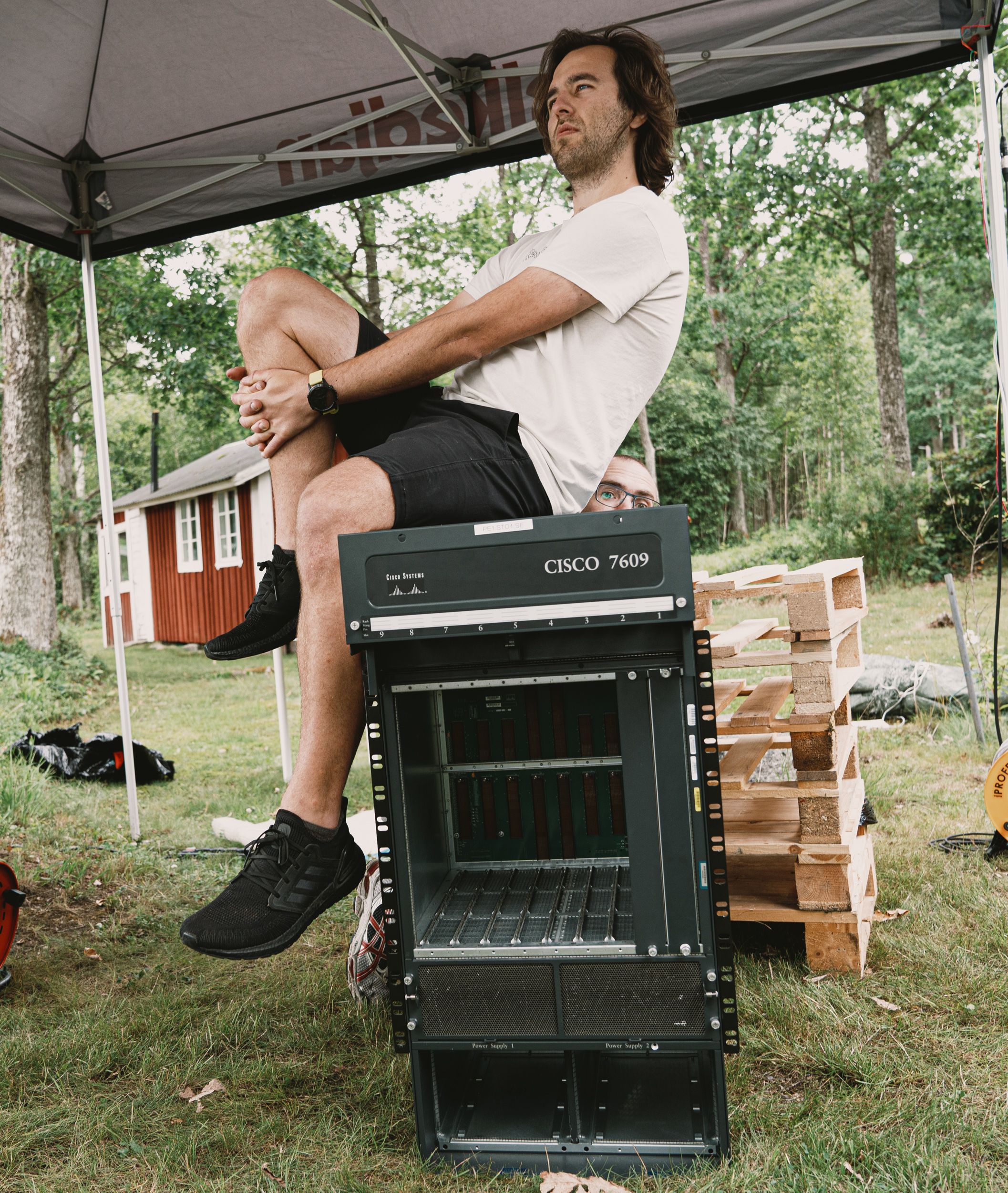
The problem here is not so much that they wanted to build something aesthetically nice but that they didn’t go far enough. If you’re going to have useless hardware, why not explore the concept further rather than a “look but don’t touch” visual display of garbage hardware? One of us started joking about converting one of the old core routers to a beer tap and Wberg realized that he might actually be able to source one of the routers of the same model that used to sit in that PoP. Fast forward to 2020 and we start discussing the actual reality of converting a Cisco 7609 into a beer tap. Wberg works as a network architect and has had this idea for a long time, converting a router to a beer tap but it’s not like you can convert 1M EUR of hardware into a beer tap. Time did it’s thing and Wberg was able to source a used 7609 in working condition, I don’t think we ever imagined this actually happening but now Wberg posed the question “I have 100 kilos of core router, what do we do with it?”
Plan of attack
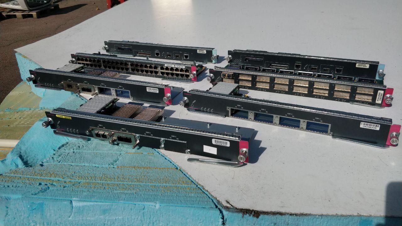
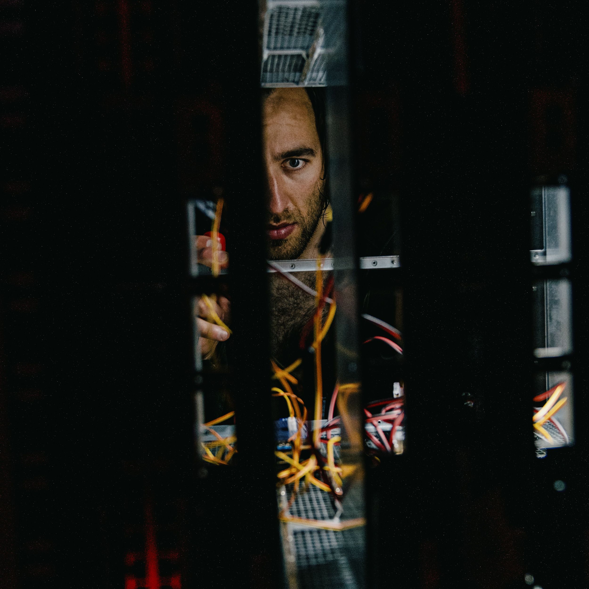
The first was figuring out what the end result was going to be. If we wanted a beer tap then we had to modify the machine quite heavily and it was unlikely to ever work again, however, if the router wouldn’t run then it wouldn’t look as visually pleasing as a real one does. So it was either powering this beast and figuring out how to pipe in beer into a live 7609 OR re-building all the parts that provided visual indication which made it look active. The decision seems easy, why spend a huge amount of time on rebuilding a device that already works? Well, the moment you turn the router on and hear the fans it’s obvious that the only approach is to rebuild it. Behind the cable management tray there are two “fan packs” which each packs 4 x 48V industrial fans. These fans are built for reliability and air throughput, not for a low noise profile. On top of this, if we were to use the existing line cards we would need to ACTUALLY feed traffic on the ports for the activity LED to look busy.
With that in mind, how do we go about rebuilding this thing? The constraints are:
- All LEDs on the front needs to work
- Ethernet cables needs to be connected
- Fiber cables needs to be connected
- Can’t sound like a jet engine
- Preferably controllable intensity of the ports
At this point in time we still believed in the idea that we could salvage the existing LEDs and build a jig that would power them to avoid having to rebuild EVERYTHING. For that reason the approach that made most sense was to remove the unnecessary parts of the line card and keep the structure and LEDs. Since this trash was built in the early 2000s I was skeptical towards cutting these line cards but Bengan & Summa did not let themselves be persuaded by my thoughtfulness about toxic dust and cut right through all of the line cards, removing approx. 70% of them.
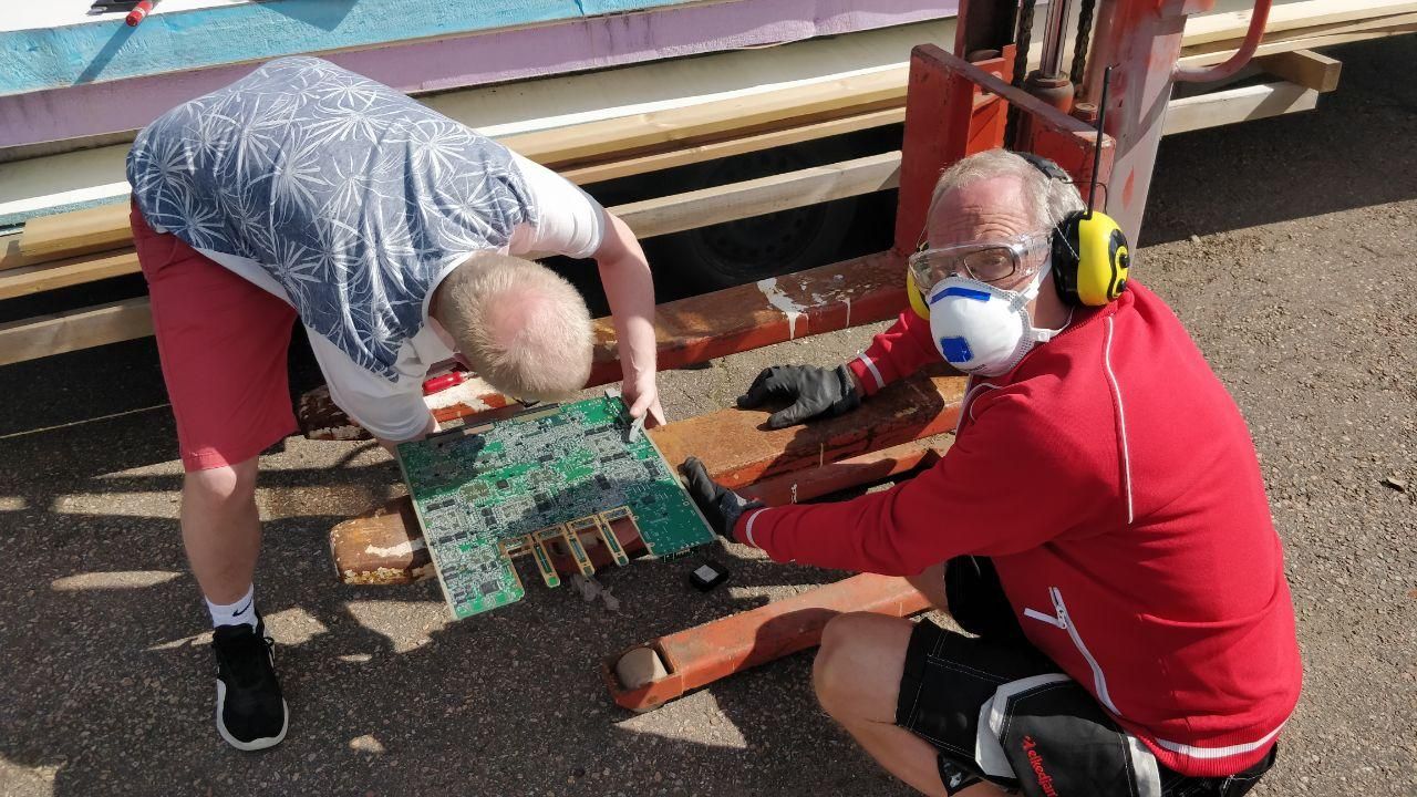
It should be said that since this was during 2020 I wasn’t able to travel to see the line cards in person and relied on Wberg’s analysis of the cards to help guide the project into a feasible solution. Once Wberg got back to Stockholm, he and Love (king of electronics) scheduled a quick session to examine the line cards and the outcome was sadly not that positive. Not only was almost every line card different but each LED was a green/orange one without on-board dimming meaning that we would have to build 7 different jigs with tons of standalone PWM chips and shift registers. On top of that, if we somehow blew one of these LED’s the replacement would be a pain as the baseboard was an early 8 layer board with hidden traces.
Time for PLAN B. I had worked with APA102 previously with the cube and found them easy to work with (except for electrical noise) and encouraged Wberg to buy a strip to play with to explore what could be done if we replaced each LED. Wberg was quickly able to make the strip work and became equally confident that using a separate LED strip was the way forward in this case. Wberg initially explored just attaching the LED strip straight against the profiles on the chassi but the pitch didn’t match up which meant that the LEDs were unaligned from the front profiles. We probably could have gotten away with this but it didn’t look perfect, you could tell that this was a fake and that the router wasn’t booted. If we already gone this deep, going deep enough to make it look perfect is the only option.
Finding solutions to constraints
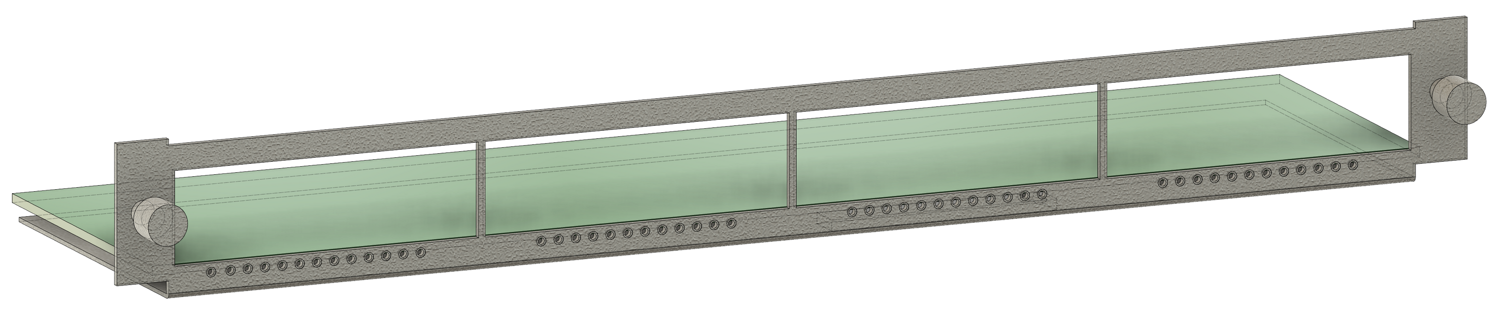
So how does one go about making it perfect? At this point neither me or Wberg had any ideas. There were tons of constraints here, especially with the 48 port cards. The 48 port card have about 6mm of clearance underneath the baseboard with 4 mm of clearance against the outer chassi meaning that whatever solution we created it would have to be small. We started by sketching out the line card with most constraints in Fusion360 to have a shared reference of the measurements.
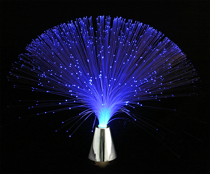
At this point Love asks me: “Why not use optical fiber?”. I was initially dismissive of this idea, thinking of fiber as more as an expensive medium to transmit data but after thinking about i stumble on a link for a “star ceiling”, essentially someone piping tons of 3mm fibers into small holes in their ceiling for a very unique light. This time the question actually hits me, why NOT use fiber? Optical fiber is BUILT for this purpose. It’s often flexible and focuses on one thing: transmitting light over distances. If we could mount a fiber cable against each individual APA102 light on the strip, could we just pipe the light to where it needed to be? I ordered a bunch of different fiber cables from AliExpress and of course the transmission was exactly what we wanted.
Creating the parts
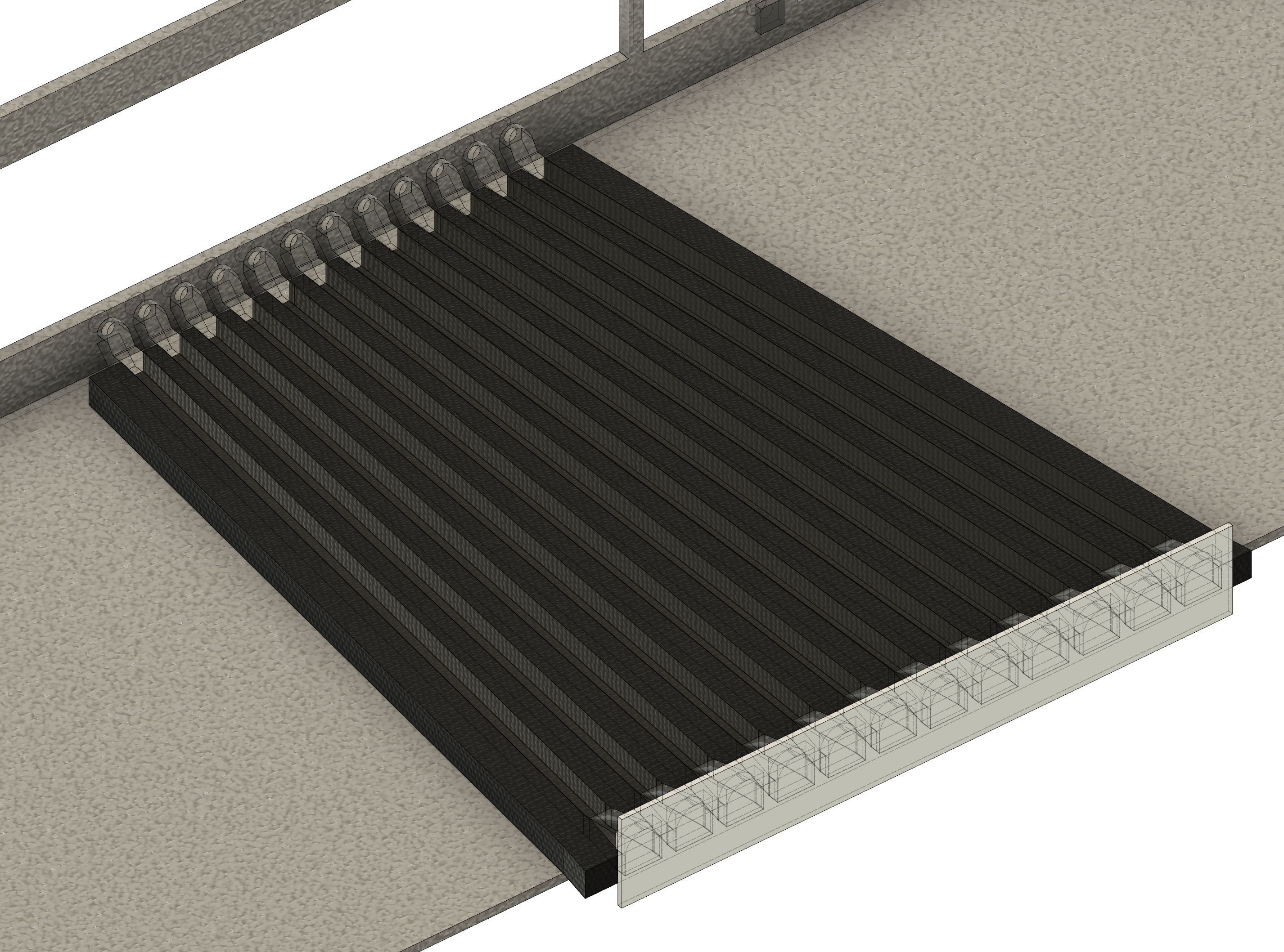
With this problem out of the way, the next problem was “how are we going to mount the fiber cables against the chassi”? We need to somewhat precisely align the fiber cable which immediately had me reach against 3D printing. What if we printed a “focuser” that served both as protection and alignment for the LED strip but also as a holder for the fiber and a “receiver” that would be glued against where the normal LED would have been positioned. Since I didn’t have the actual line cards in San Francisco, Wberg bought a 3D printer in Sweden to allow us to iterate remotely.
Let’s start with the focuser. I toyed around with a bunch of different ideas on how to design it and settled on a cradle that would hold the strip with a plate that partly locks in place and is held with screws against the focuser. Getting here took a couple of iterations but once I explored the “teeth” concept and did a test print which made it was obvious that this was the design to go for. The idea was to reduce the part count as much as possible and to be able to increase the structural integrity in order to lower the amount of stress we would put on the LED strip. One added bonus is that this could be printed with a minimal amount of supports, only requiring supports for the hex nut holders. Being able to avoid supports allowed us to spend less time on finishing the holes that would hold the fiber as the press fit would be equal across the receiver.
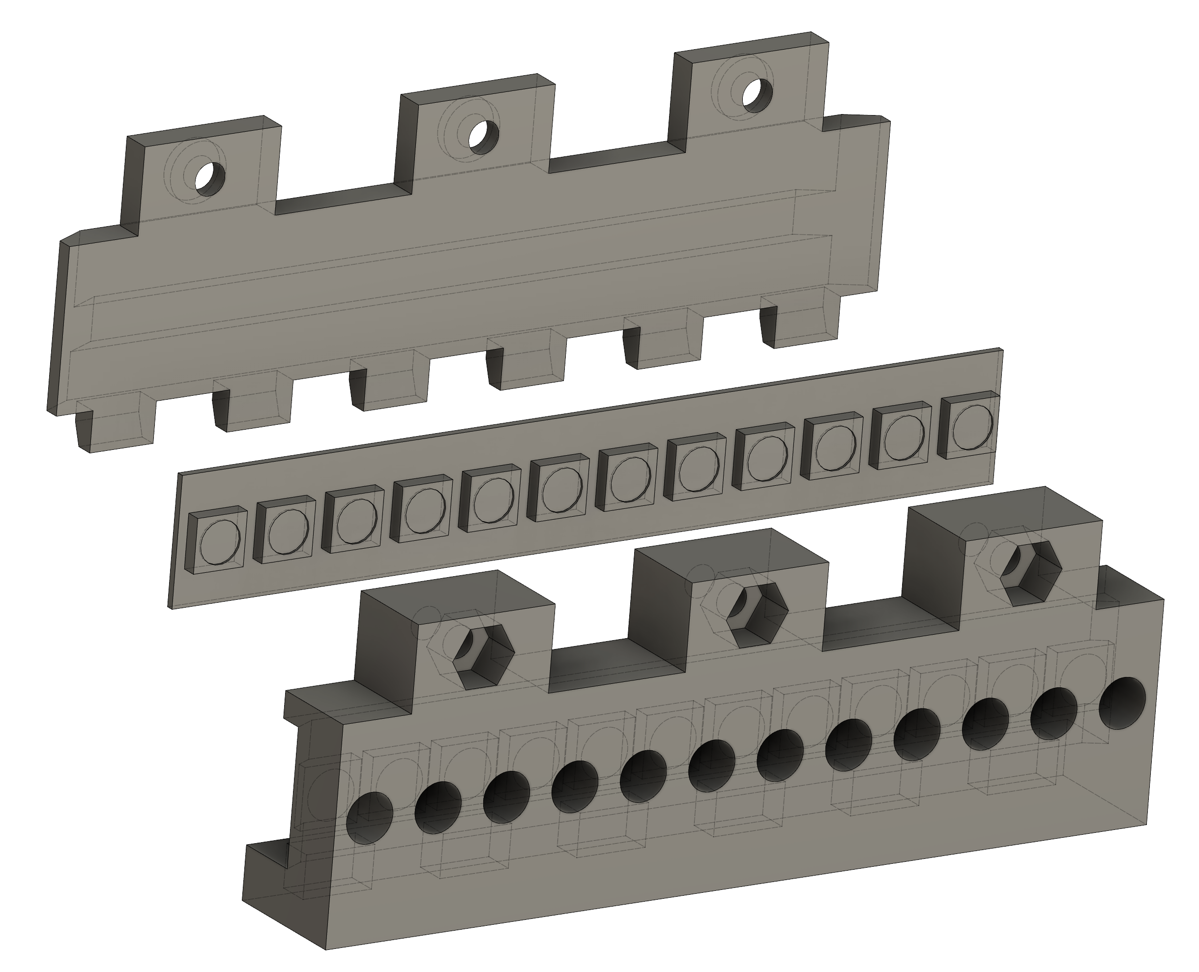
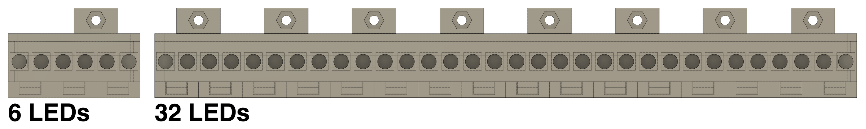
What was frustrating was that all line cards have different LED counts (12, 5, 5, 5, 5, 50, 50) and when testing tolerances it was so hard to keep track of what value I had changed after Wberg printed the part. 3D printing can be weird with tolerances, especially with holes and PETG and prior to Wberg learning how to properly finish the parts. Eventually I realized that the “count” of LEDs really didn’t matter, if I could build a part that worked for 5 we could extend that one. This led me to re-designing the part completely using parametric design. For all you people that 12 months ago had no idea what this even meant, imagine deriving all the measurements in the CAD software from variables to the point where I can type X LEDs and the sketch updates and create the amount that I want. The beauty of making this parametric is that it was much easier to iterate on what values we actually needed to get “press fit”, as in the friction of the hole holding the fiber without having to glue it together. This example below is generated from the APA102 strip sketch, by extending the LED variable, the strip changes size and this model scales up to fit that strip, deriving the measurments from strip.
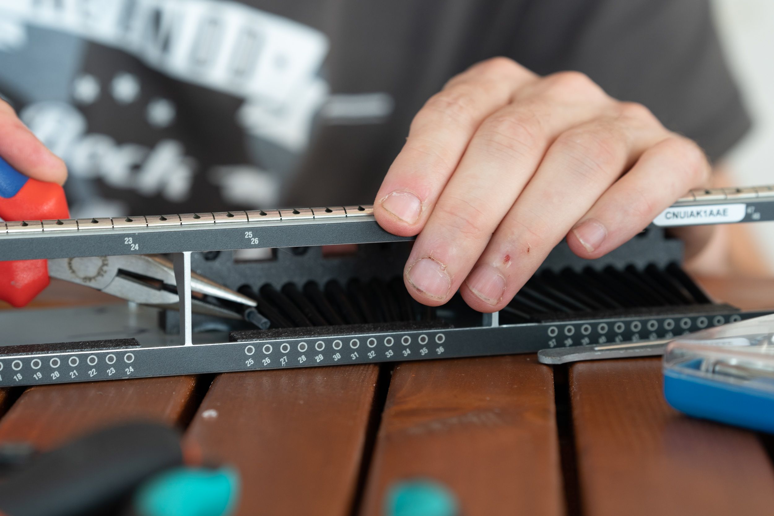
The receiver parts seemed easier on paper, so easy that Wberg who’s new to 3D printing and CAD managed to make all the ones EXCEPT for the one that would sit underneath the 48 port board. The available space underneath the 48 port board was so tight (5mm) that my approach was to just build a caddy and use epoxy glue to fixate the fibers. This seemed like a really messy idea and I didn’t find a good way to make a cable that’s 4,2mm in diameter fit in a 3D printed caddy with 0,8mm to go and still provide strength. We went back and forth on this issue until one day where Wberg flipped the baseboard in the line card upside down and slotted in the ethernet ports into the chassi. Of course it actually fits because the ports are symmetrically placed. That gave us tons of extra space to work with (now closer to 7mm) and only required drilling some holes into the baseboard. After some designing we found that stripping the fibers of cladding and using only the core allowed us to use the most amount of 3D printed material, which added to the stability and press fit. The only remaining thing to do was cutting and stripping over a 100 optical fibers and mounting this thing which we saved for a meeting in Anderstorp.
Writing the software
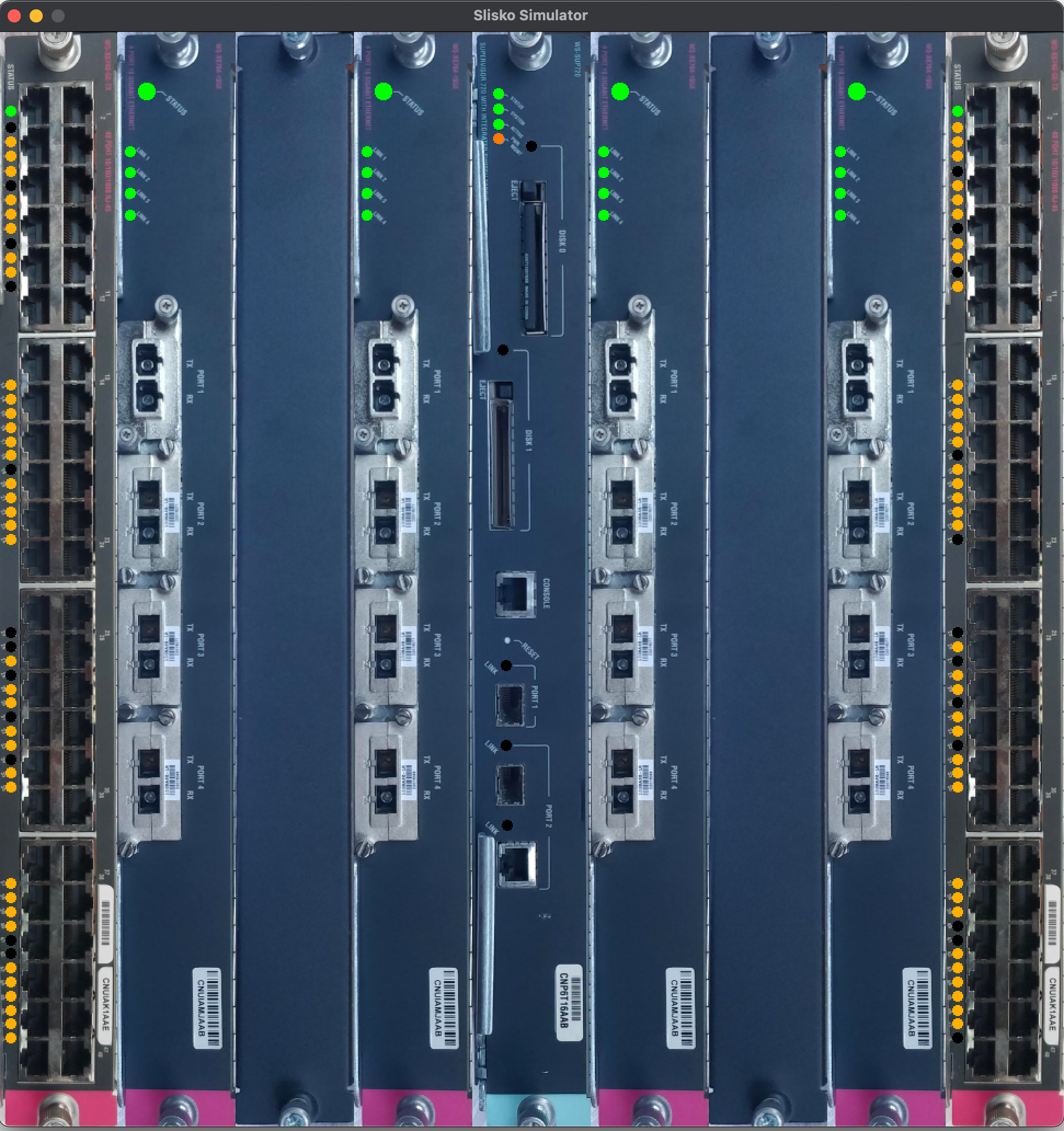
Since we basically killed all logic in the router we had to create something that could mimic how a router would behave and do more exciting things than just that. I picked apart a lot of the code that I wrote for nocube and wrote something new that focused specifically on the router called slisko. The intent here was to have a piece of software that ran on a Raspberry Pi, used the SPI port to drive all the LEDs and serve as a web server where one could control the different behaviours of the router such as color changes and strobe.
The software is based around the idea that there exists “LEDs” which are then repackaged in various slices with references in order to have multiple ways of querying the LEDs. You could for example ask for all the system LEDs that belong to a SUP720 card.
for _, port := range c.GetCardOfType("sup720") {
    port.Labeled["system"].SetClamped(0.0, 1.0, 0.0)
}
However if you wanted to query all LEDs of the entire device as a whole, ignoring the realm of line cards you could get all of them visually sequentially mapped.
for m, port := range c.LEDs {
    if m == int(l) {
        port.SetClamped(1.0, 1.0, 0.5)
    } else {
        port.SetClamped(0.0, 0.0, 0.0)
    }
}
I looked at some reference footage that Wberg shot for me of how an actual router “blinks”. It’s easy to think that it just blinks randomly on port activity but there is some structure to the blinking. First of all it blinks negative, meaning that the LED is always lit and is turned off on activity. Second is that there are a few distinct “speeds” of blinking rather than a curve. It looks like there are steps of 0/20/40/60/80/100 in terms of activity and the ports blinking on these intervals. Third is that there is a common clock across the ports on the same line card, meaning that I need to keep track of the blinks per line card rather than globally. I ended up creating a very simple interface in Go:
type Fake interface {
    Trig() float64
}
This allowed one to easily build constructs that can be chained, for example a random blinker that is chained into a stepped blinker interface and composed together per line card. In the end I had a bunch of different interfaces that the pattern chains together per linecard to create the illusion of proper blinking. Who knew that something simple as blinking a LED was this complex…
Assembling the insanity
Onto the preparation of line cards, as mentioned before we had to do the final 3D print and prepare all optical fibers + mount it all together. We started the week by printing out the parts and verifying fit, tweaking some parameters and then burning out the last pieces on the printer. From there it was just a matter of spending an afternoon.
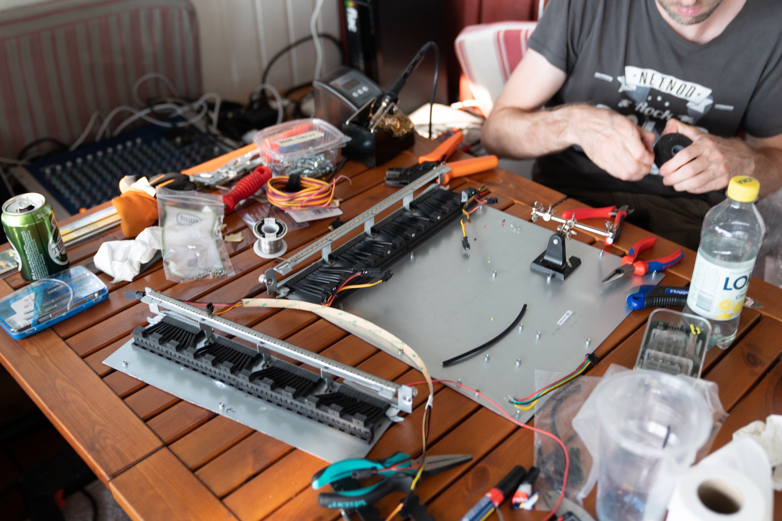
With this out of the way we could start mounting the line cards and wiring the chassis for power. It was one of those really hot nights that I never remember used to happen in Sweden where you were unable to wear anything other than swim trunks at midnight which lends itself well to a night of cabling.
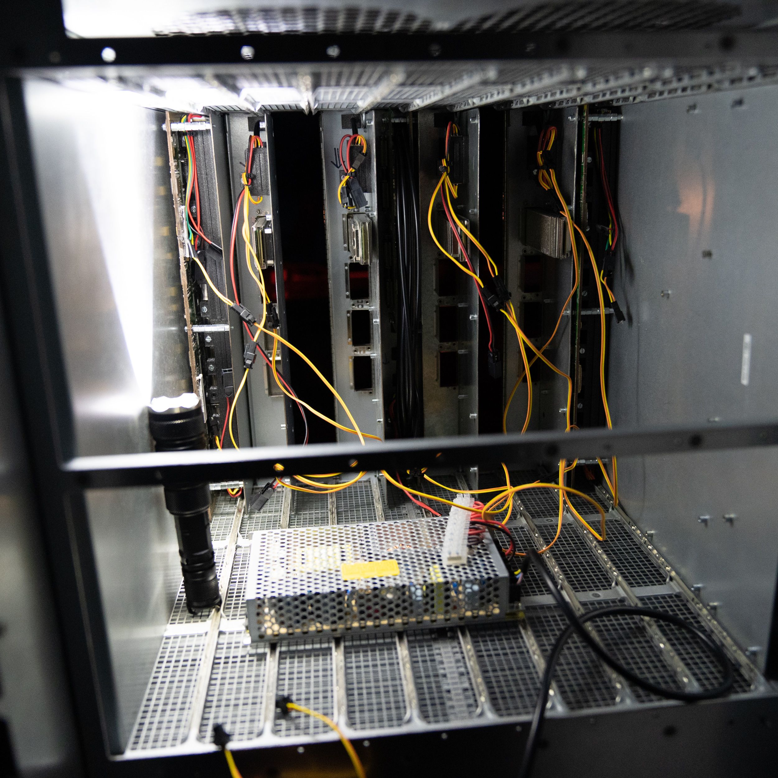
After a few resolderings and fixes on the LED strips (soldering 144/M APA102 was 1000% less fun than 72/M) it finally started up with all LEDs working. I started adjusting the mapping in the software but noticed a flickering noise, something I’ve sadly encountered before with the cube. The flickering was random, more pronounced on certain dimming frequencies and changed depending on how the cabling was routed which indicated electrical noise. What I didn’t account for is the increased electrical noise that the denser APA102 generates, partly because you have over a 100 sources of PWM on the same power line without any smoothing. This one took a while to figure out as we experimented with a range of different approaches to solving this issue but the solution ended up being as simple as soldering a capacitor to each power input side of the 48 port cards. After reading up more on this issue it seems like this is quite common with dense APA102 (email me if I’m wrong) and adding capacitors to the power helps keep the signal through the strip stable. If you are searching Google like I did looking for how to fix electrical noise for APA102: Add 1000uF of capacitors to each end of your strip, absolutely solves the problem.
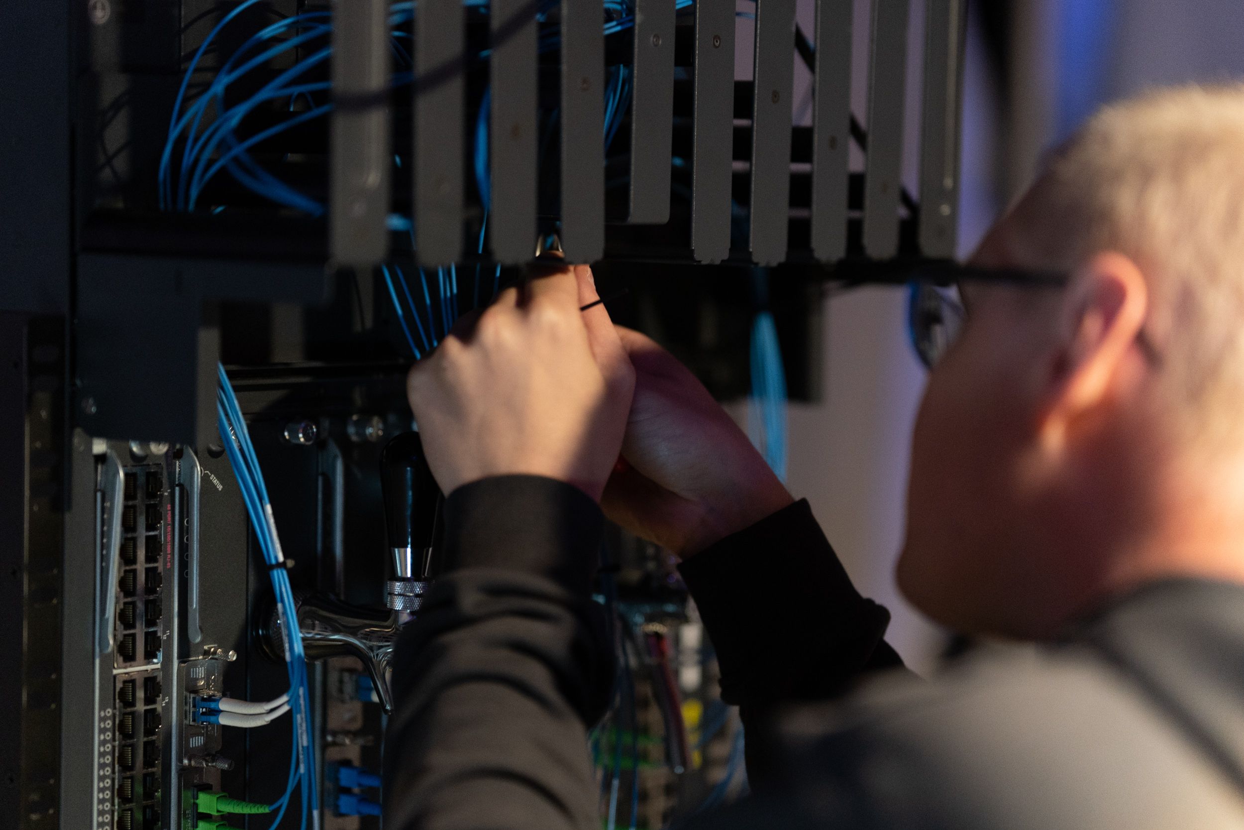
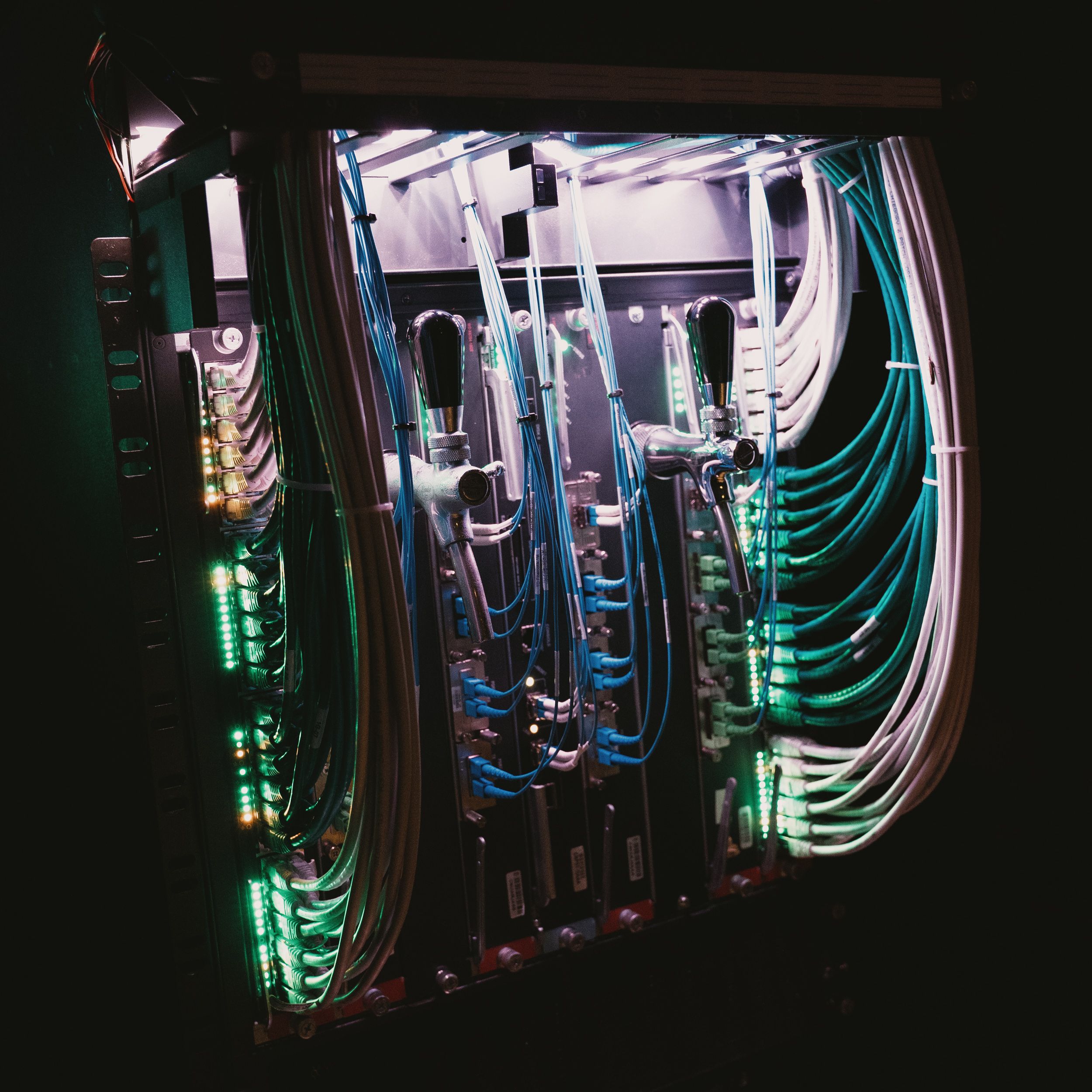
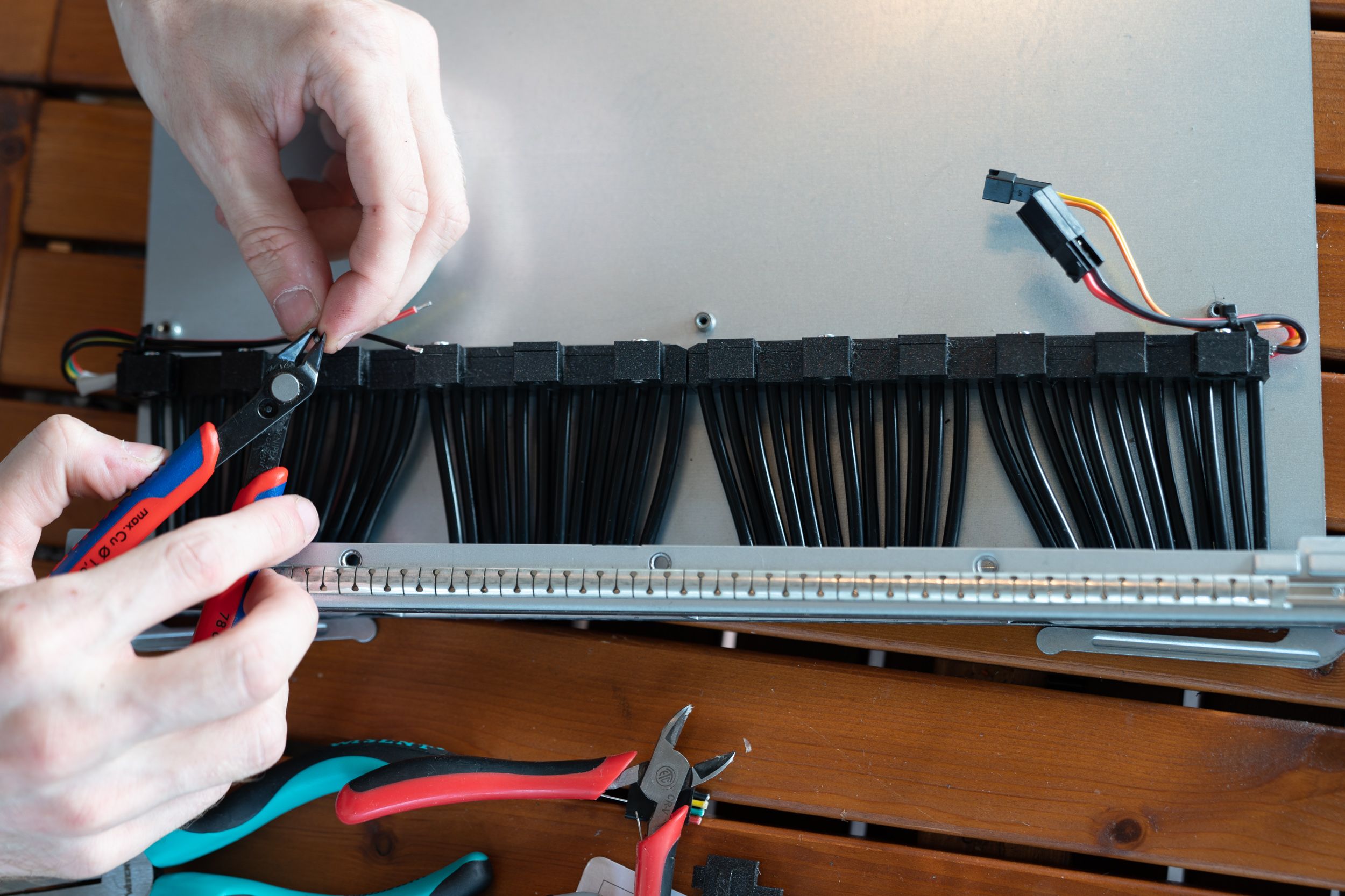
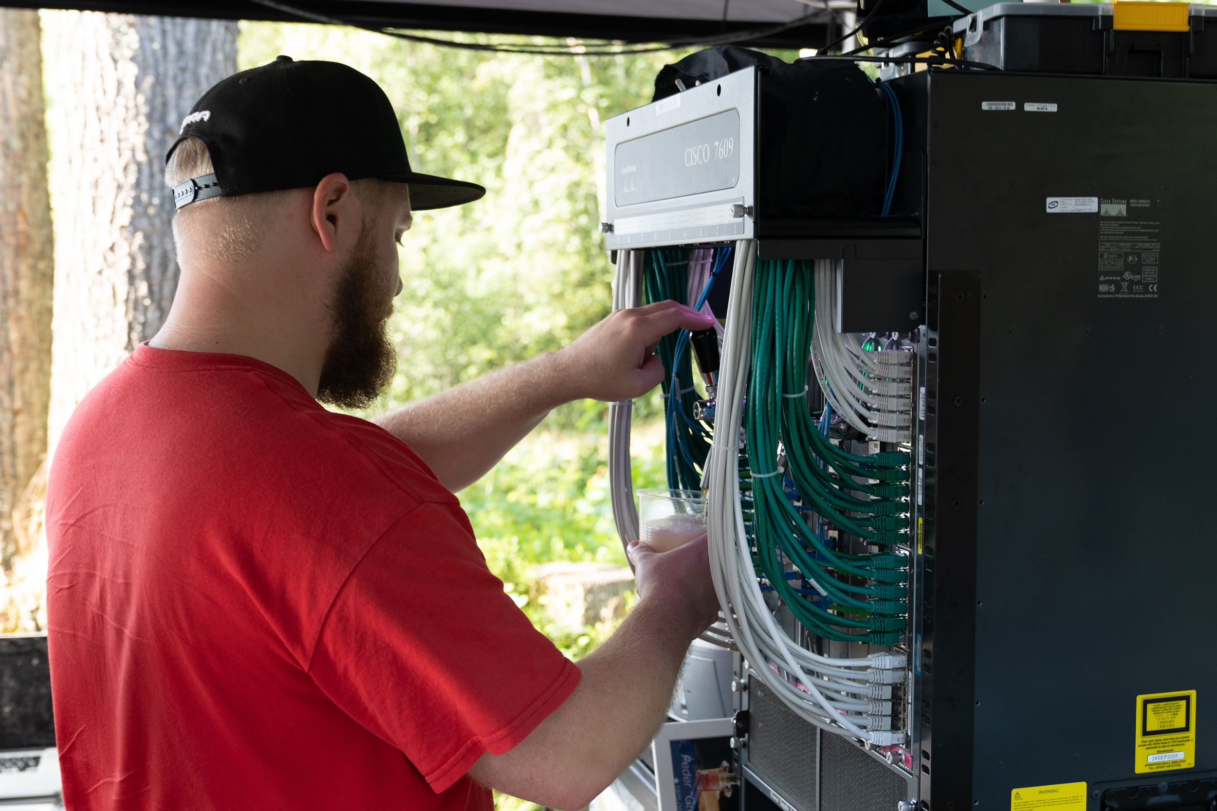
Summalajnen got the honor to “brush” the router, meaning aligning all cables in a visually pleasing way, sort of like brushing your own hair but in this case network cables. We wanted all ports to have a connection for it to look like the router was active and Summa spent a good amount of time cabling and stripping the cables to look perfect. We ended up mounting a small 20 LED strip on top of the
About the beer
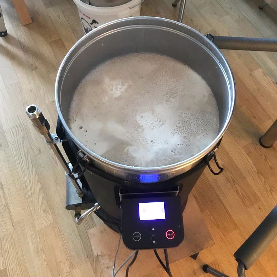
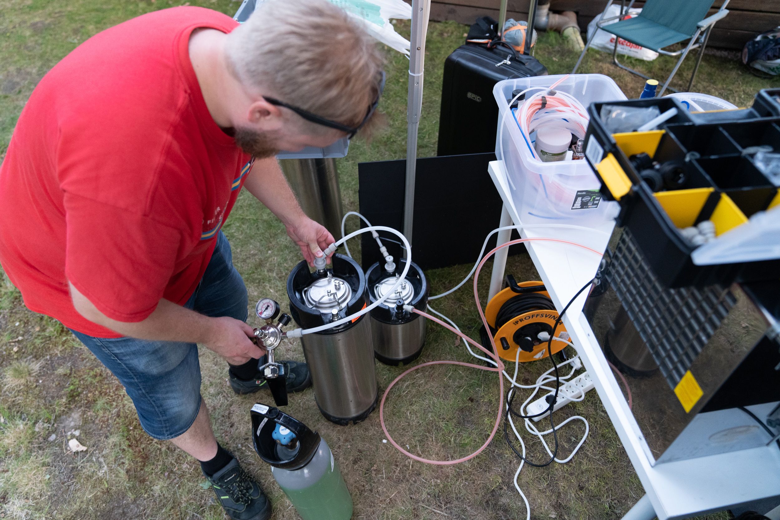
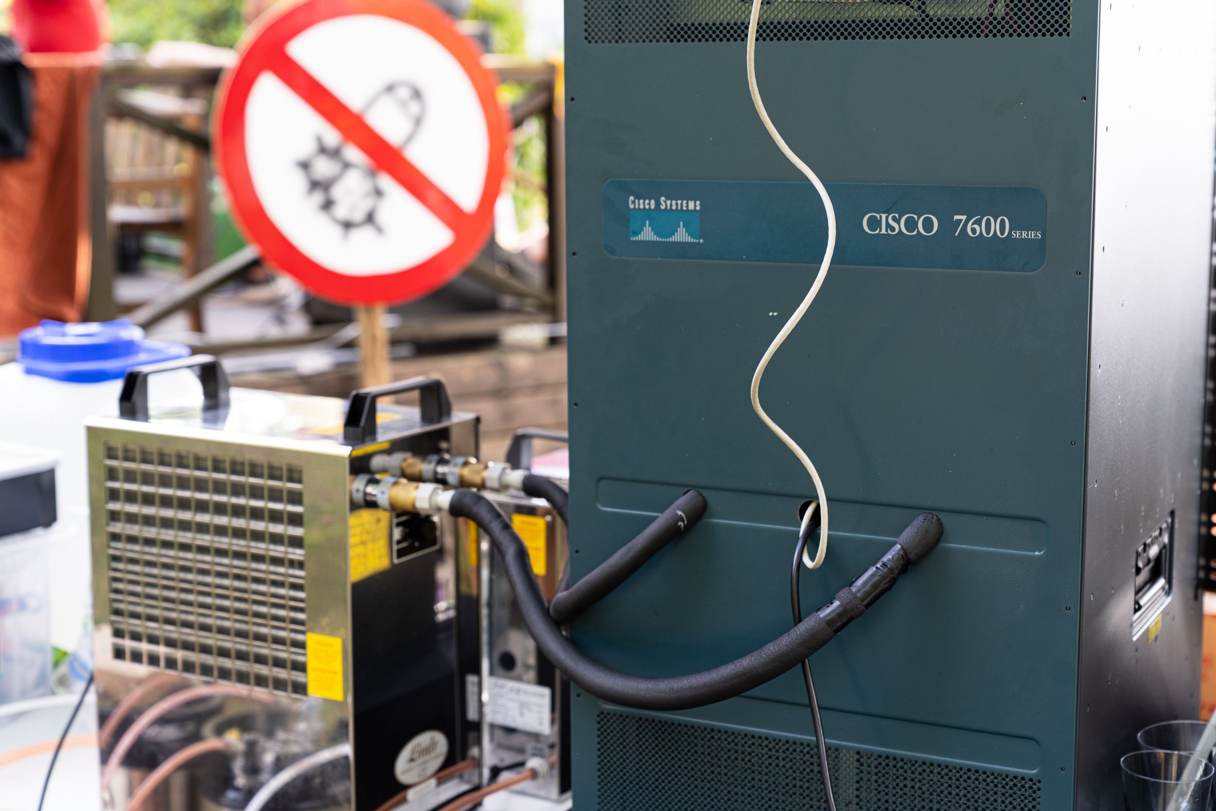
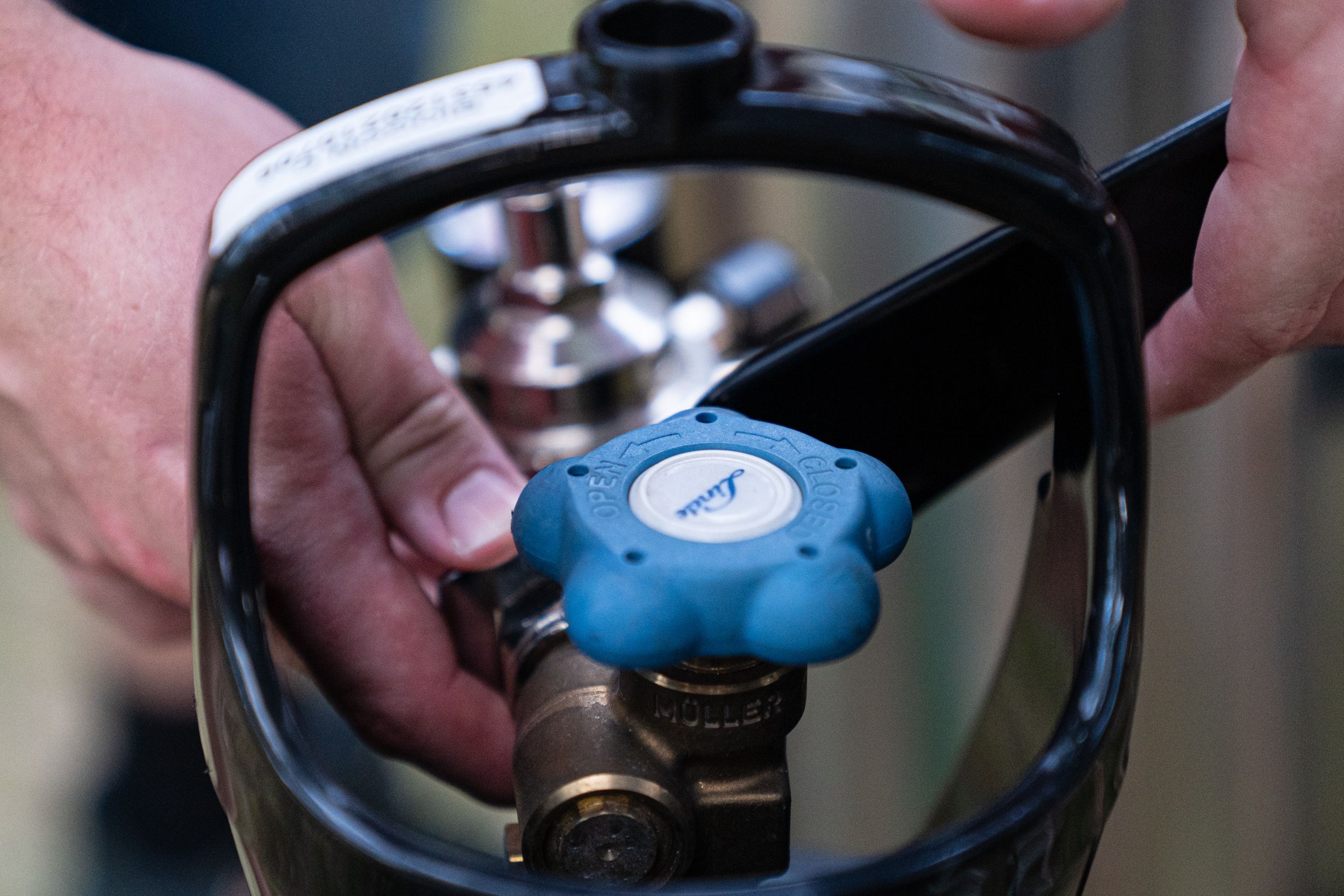
With all of this done we had Foxbat, our resident beer brewer, step in and actually connect the beer parts of the machine. Foxbat had consulted with us prior to the festival regarding how to adapt one of his tap coolers (Lindr Kontakt 40K) into more of an intermediary fridge. The Kontakt 40 is primarily built to be served out of but Foxbat came up with the clever idea of mounting “cleaning adapters” in order to fit extension tubing. A small brass connector that screws into where the tap handles on the Kontakt 40 sits, on which Foxbat then mounted an adapter that allowed connection to regular 3/8” tubing. We coated all of the extension tubing in off the shelf isolation from a hardware store to keep the beer chilled and hoped that the throughput of which we sold beer would be enough to avoid having to serve warm beer.
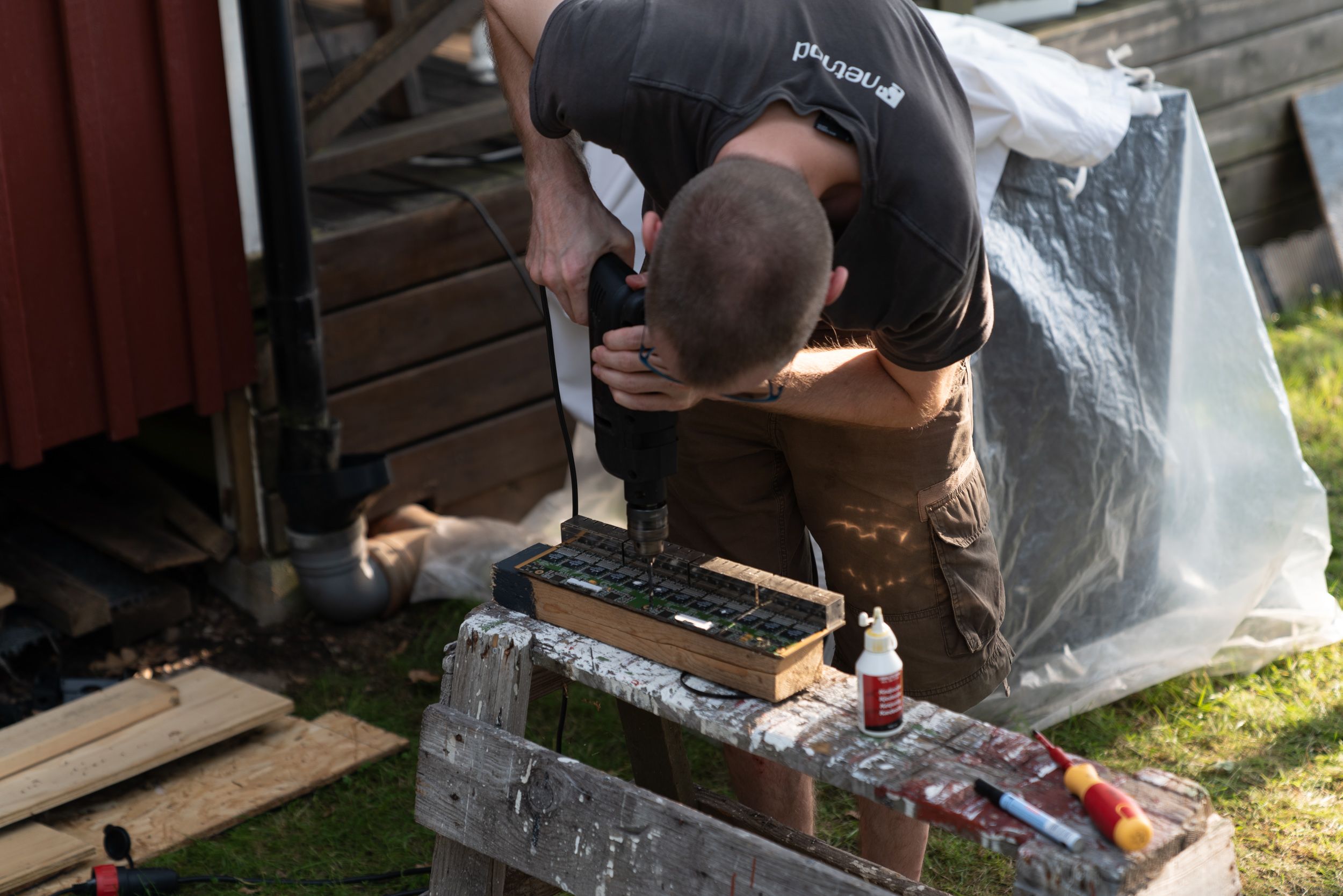
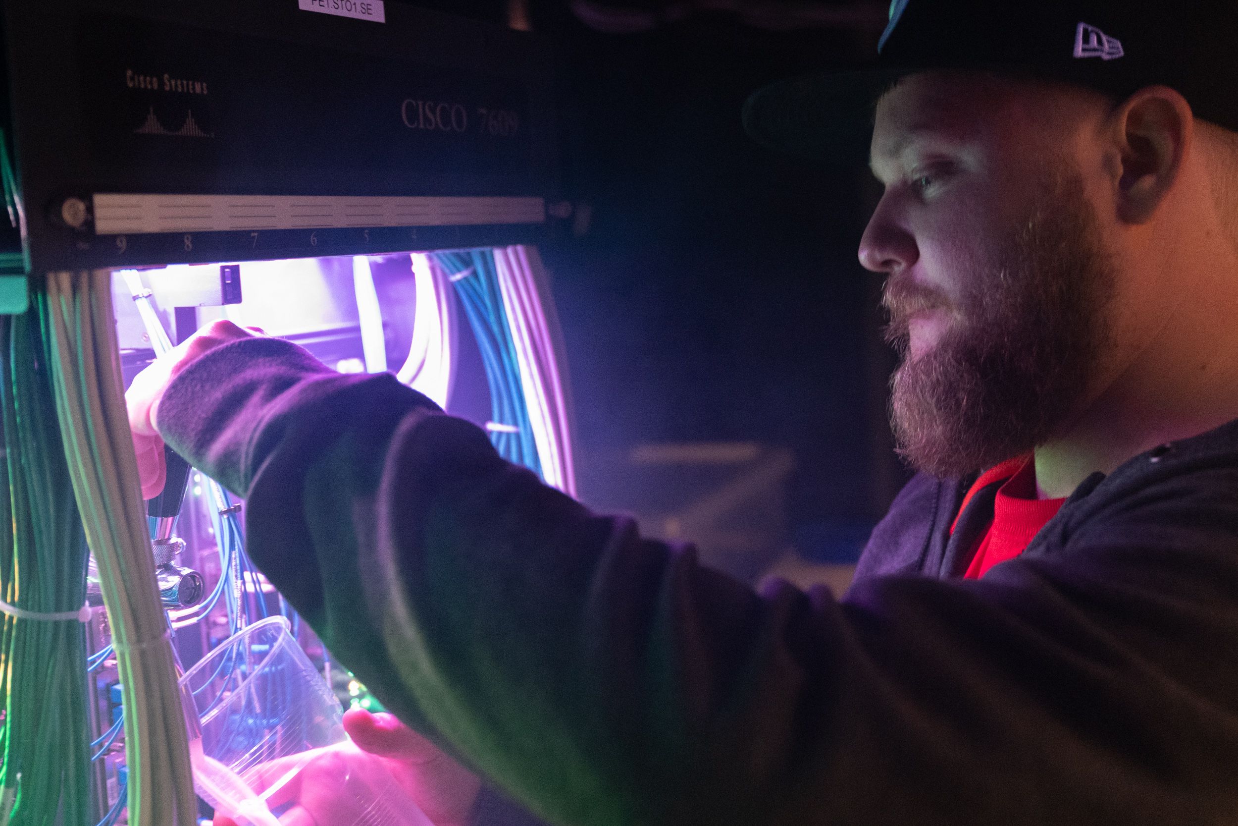
For the beer handles on the router, we purchased two chrome plated Lindr dispensers and drilled holes on two of the blanking plates which are used to cover empty slots in the router. Foxbat then piped the output from the Kontakt 40 through the back side of the router to the tap handles on the blanking plate. Almost a magical experience to see the first glass being poured from router after all the work we put into this and the fact that the adapter solution that Foxbat came up with actually worked.
Takeaways
I’m personally extremely happy about how this project turned out. It required me to pull out so many different parts of my mental toolbox and ended up challenging both me and Wberg in various ways. One specific thing I’ve come to realize is how hard it is to describe technical concepts over text. Sure, I can see a picture of a piece but actually holding the piece in my hands allows me to grasp the problem in a much more effective way than asking questions. I wish we had some sort of haptic collaborative VR setup here to iterate on these things when split across time zones but that’s for the future to give us.
I wish that we had to spend less time debugging the electrical noise. This is one of those that I should have explored in San Francisco rather than tackled at location especially since I’ve run into this issue many times in the past. It sounds so simple to solve but when trying a variety of solutions it’s easy to confuse what solution worked which extended the timeline it took to finish the router. On top of that we were a bit too aggressive with how close we put the LED strip towards the top so the soldering ended up letting go while testing different approaches. This meant that I had to resolder these strips I don’t know how many times so if I end up working with 144/M density strips again I will design some sort of connector protection in the print.
The beer tap in itself worked perfectly throughout the event, we sold through all beer that Foxbat had brewed and I think that’s partly due to how striking the piece is in reality. It’s this huge router which isn’t supposed to sit in a bar, looking like it’s powered up with two beer handles attached to it.
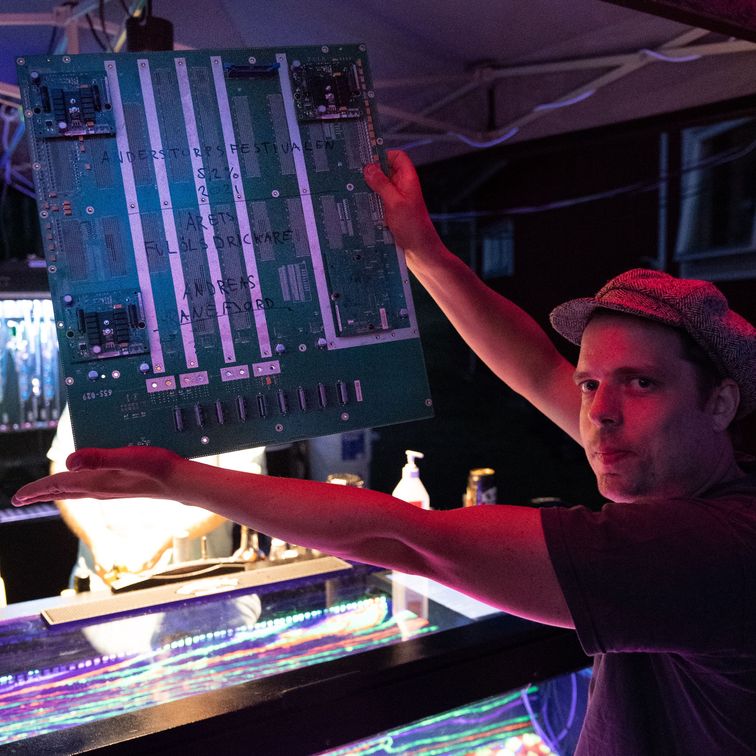
Result
You might have one more question: What happened to the backplane? Turned out that the backplane was an excellent gift to hand out to the person that consumed most beer that was considered “bad” using our grading system.