
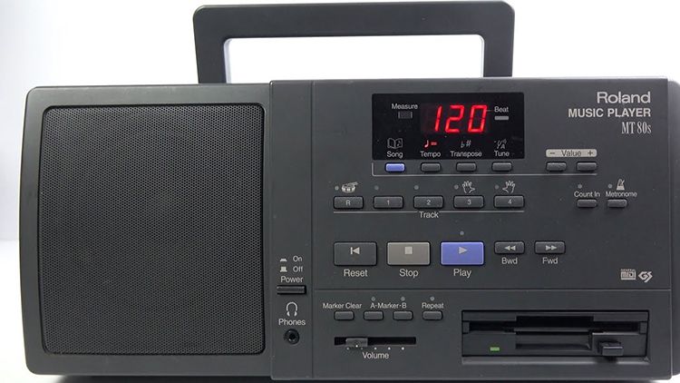
MT-420 - MIDI FLOPPY PLAYBACK MACHINE
A while back I was researching ancient MIDI sound modules such as the legendary Roland MT-32. The sound that these older synthesizers produce is extremely dated but in the right context it functions almost as a time capsule into what used to be state of the art. Take for example the iconic opening of The Secret of Monkey Island being played back on the Roland MT-32 and you’ll know what I mean that there is a specific sound that these makes that has gone out of fashion
Synthesizers of today sounds amazing. There are tons of analog synths and newer digital wavetable synths with oversampled filters on the market today both which overcome and emulate the essential characteristics of older synthesis. Compared to this the MT-32 produces a sound that is a relic of the technology of the time. It’s based on the same synthesis approach of the Roland D-50, namely “Linear Arithmetic synthesis”. The idea is basically that you combine short PCM samples and subtractive synthesis to create sounds, where using the subtractive synthesis as a base layer and the PCM samples as an embellishment would create a more interesting sound. This technology was mainly invented due to the limitations of memory at the time, making it very expensive to produce synths based solely on PCM samples.
The MT-32 was a consumer version of D-50 and quickly found use by games at the time. Back then it was not feasible to ship streaming audio (again due to the size limitations of floppies) which meant that games took upon themselves to interface with soundcards and modules like the MT-32 to generate audio. Due to the complexity of manually figuring out what sounds every channel would have per popular sound module, General MIDI was introduced in 1991 as a way of creating a standard set of instruments that you could expect from every sound module. Roland followed with the Sound Canvas 55 (SC-55) which shipped with General MIDI and a large variety of new sounds, while the device lacked some of the flexibility in programming that the MT-32 offered it improved on the clarity of the sound.
Shortly afterwards the CD-ROM became popular which allowed for CD quality streaming audio on personal computers, essentially removing the need for separate audio synthesis in the form that the sound modules had offered. On top of that the soundcards that shipped with PCs for PCM audio contained stripped down versions of these synthesizers which eventually got replaced by software only synthesis when CPUs became fast enough.
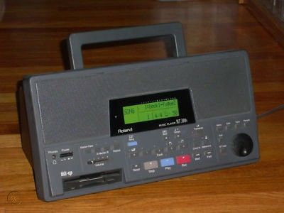
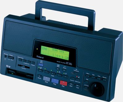
The MT-80 followed by the Roland MT-300, an even more pimped out version with added features and stereo sound as the concept became fairly popular as a way of practicing music with virtual instruments.
Just seeing these horrible devices made me instantly scour eBay to see if I also could acquire a piece of history with these boxes of grey plastic anno 1996. Sadly they seem to start at around $200-$300 on eBay and that’s before you even factored in the cost of finding a floppy drive that you can replace the most likely non-working one with. I hosted a couple of cassette listening sessions at ATP, as a tongue-in-cheek against the desire to play vinyl only on rotary mixers and thought it would be a great sequel to play some horrible tracks from floppies instead. Since the price was a bit above my taste, the only thing left to do was to build it.
Refining the concept
Starting out I’ve always found it helpful to decide where the boundaries are. If you set out on a project to build something with the inspiration above there are tons of directions you could take but intentionally setting limits makes it more clear what tools and processes one needs to use. For this project it was clear early that:
- The device should have a physical interface with real buttons. No touchscreens.
- The device needed to use floppies
- Bitmap displays was out of the question, if the device needed a display it would be either segment or character LCDs.
- The device needed to hide the fact that it would be a repackaged Raspberry Pi.
- The device should not have built-in speakers, focusing only on the playback as if it were a component of a stereo system in 1995.
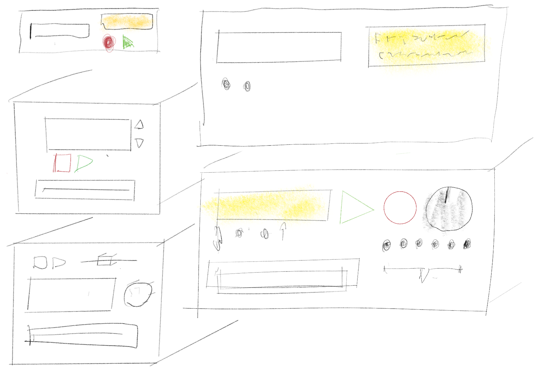
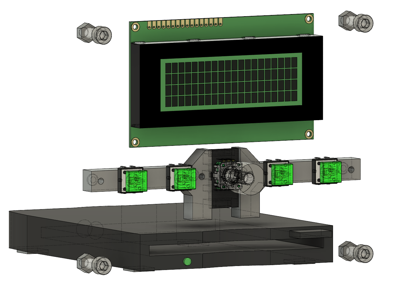
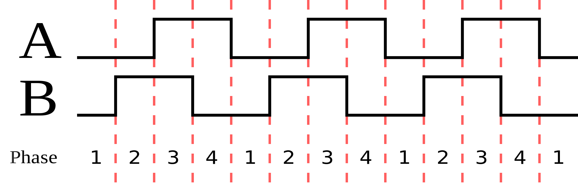
It was then just a matter of finding some nice components that seemed fun to use. I wanted an encoder and stumbled on a rotary encoder with a RGB LED inside, while fancy I felt that it would be a great way to signal the state of the device so I ended up ordering it. For the buttons and LCD, Adafruit had both for a reasonable price so I used these while sketching. I also found a really cheap USB floppy drive on Amazon which I bought along with a 10 pack of “old stock” Maxell floppy’s. Sadly 9 out of 10 floppies did not work which had me order a 10 pack of Sony floppies from eBay which worked better. I think this shows how there was an actual quality difference between the floppies back in the days as Maxell just hasn’t held up as well as Sony.
Designing the enclosure
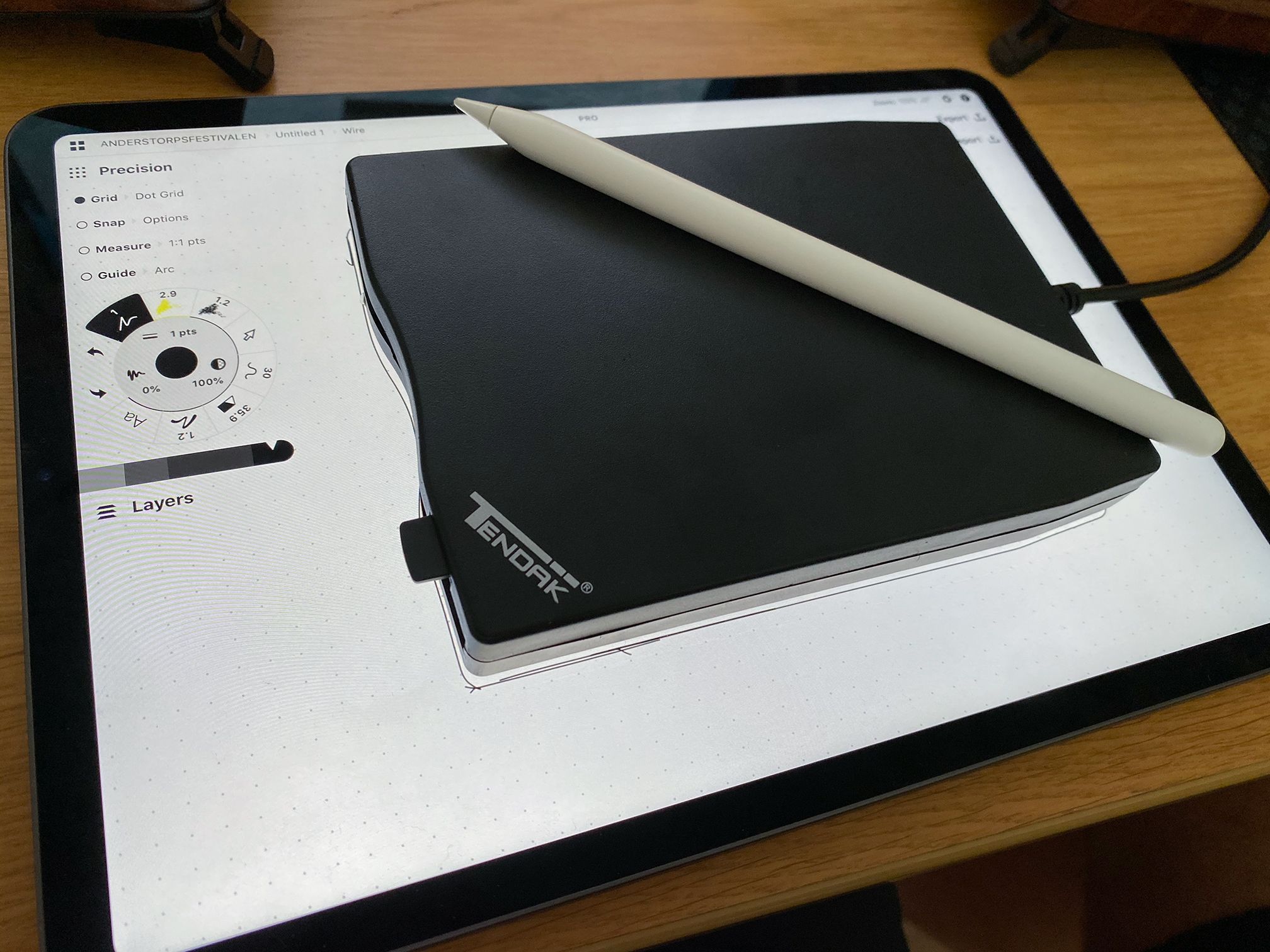
Starting from this concept it was just a matter of opening Fusion360 and getting to work on fitting the components. As usual I would be 3D printing this enclosure and to retain structural integrity I tried to minimize the printed part count, instead opting for larger printed pieces and being smart around how I designed the enclosure to fit the pieces.
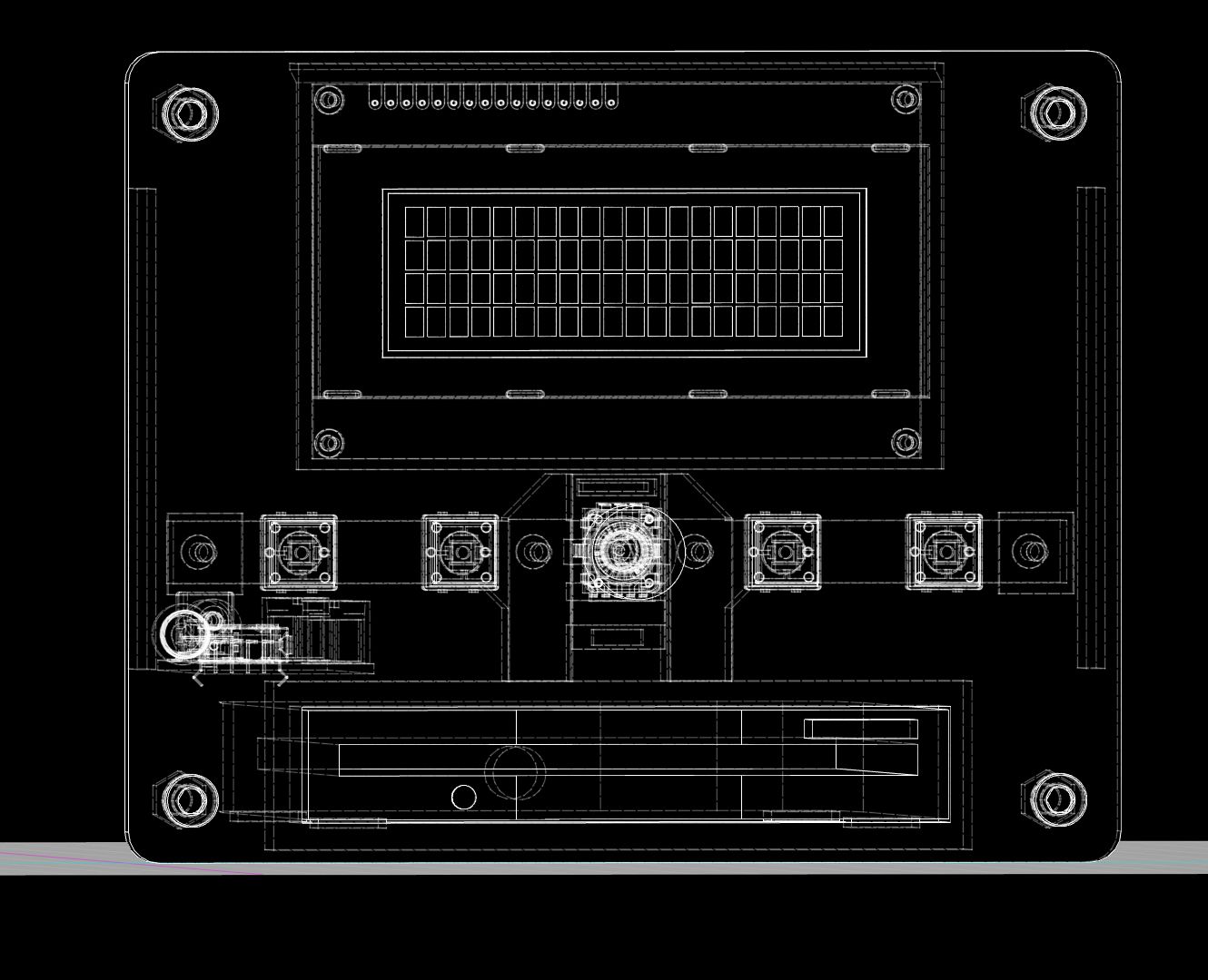
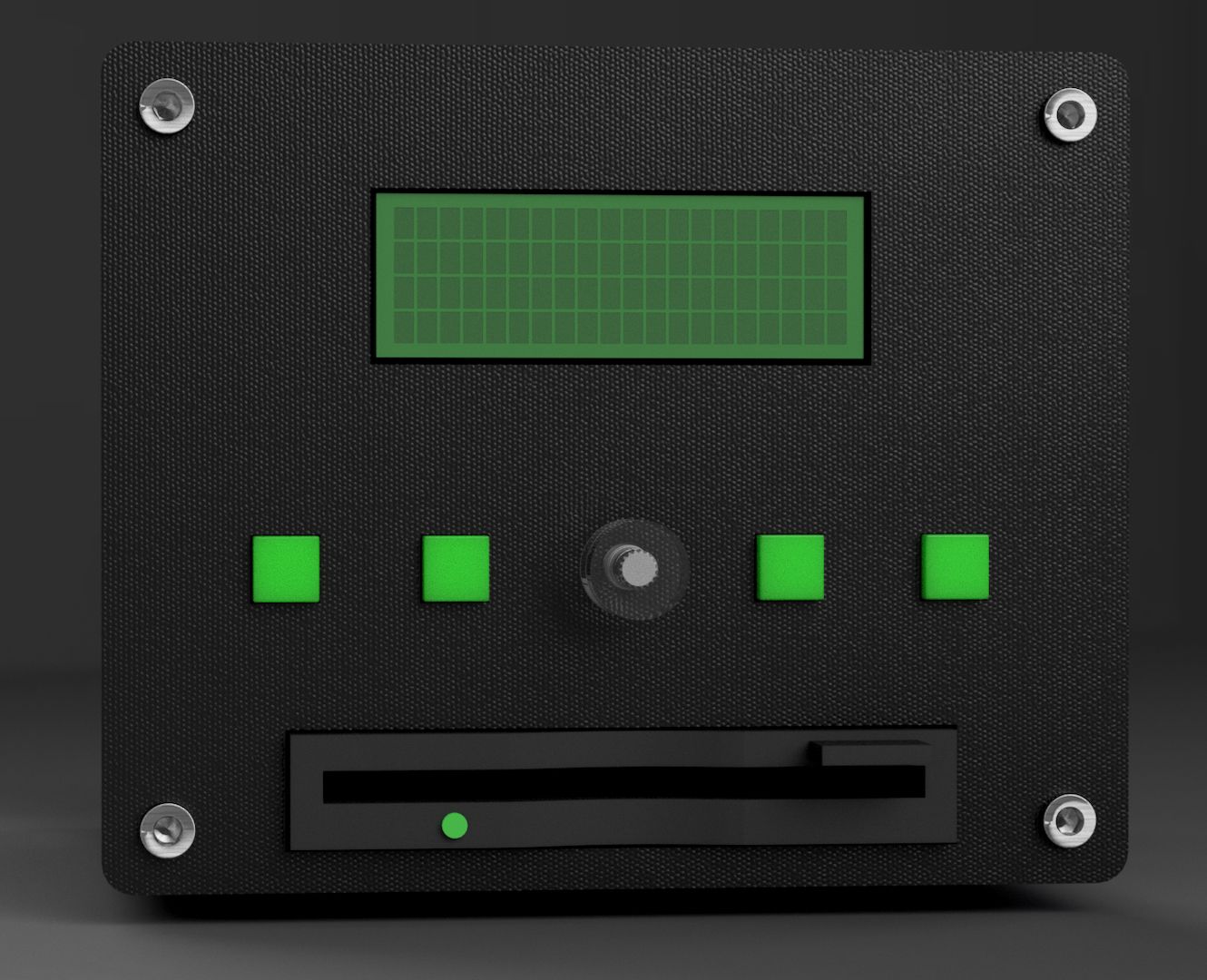
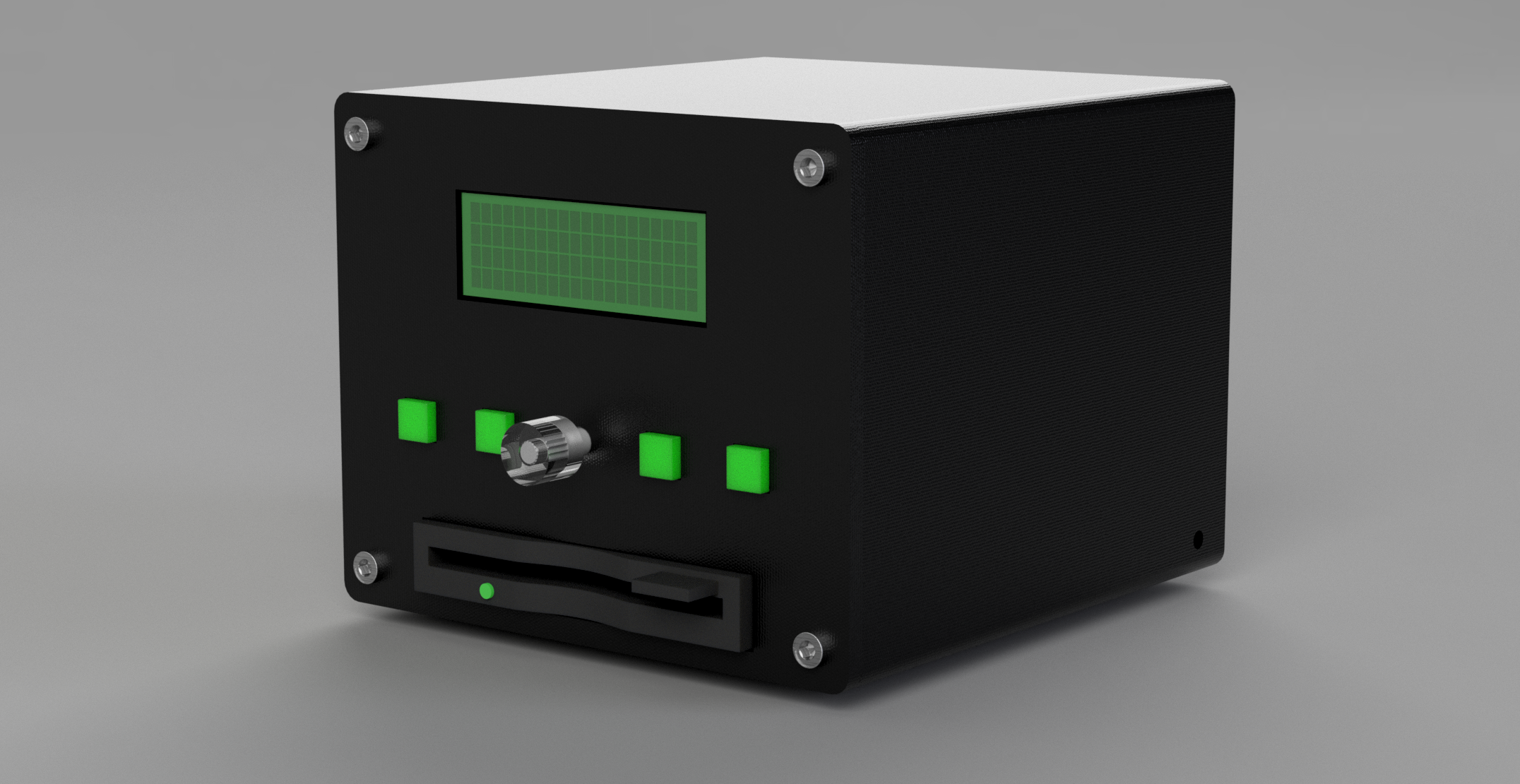
I started with the front panel as it would hold all the buttons and the encoder. As you can see I deviated somewhat from the concept as I realized the LCD has tons of baseboard padding that I would had to hide somehow. For that reason I couldn’t place the encoder to the right of the display without making the device unreasonably wide. Experimented with a couple of different aspect ratios and settled on something that’s “almost” square with visibly rounded edges. The reasoning here is that the device will have more depth due to the floppy so if the front panel was square it would break the “cube”, hence why it’s a tad wider than tall as it stands.
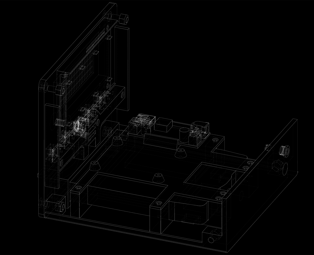
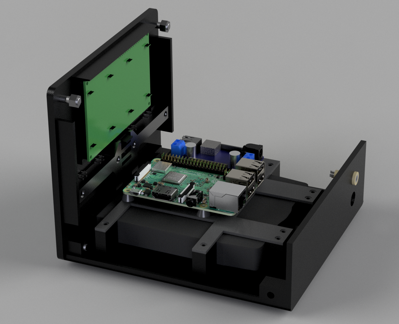
The panel went through a lot more iterations compared to what’s shown here but it’s hard to show every iteration in a great way. I had to consider how the electronics would fit and where to put the Raspberry Pi for it all to make sense. Since the floppy is the deepest part of the device I placed it in the bottom in order to be able to build the rest of the inner workings on top of the device.
With that done I sketched out a baseplate with walls that would hold the floppy in place and a layer plate which mounted on top of the floppy. Although this took a lot of iterations to get right with the fit and all the screws it was a pretty straightforward piece once I knew what components I wanted to use. Initially I envisioned the Raspberry Pi being mounted straight against the back panel with exposed connectors but it felt weird to go through all this effort only to expose that the device is just a Raspberry Pi with an ugly screen, so I added a buck converter together with a 3,5mm connector in order to fully enclose the Raspberry Pi.
The last part was to add a cover with the correct sinks for M nuts and make sure that the rounded corners extrude all the way throughout the device. Here I experimented with a slanted case as it would be fasted to print but the device ended up too much like a 80s Toyota Supra with popup headlights so I skipped that idea and came to terms with the fact that this lid was going to take a good amount of time to print.
Making the panel work
Initially I envisioned this connecting straight to the GPIO of the RPI. It’s just 4 buttons, a serial display and an encoder with an RGB LED inside. On paper the RPI ticks all of these boxes, hardware PWM, interrupts, GPIO and serial output. Using all of these in Go is another story however. It turns out that the interrupt / PWM support for RPI is actually quite “new” in Linux with two different ways of approaching it. The old way was to basically memory map straight against the hardware and manually defining the interrupts with the new solution providing kernel interrupt support for these GPIO pins. Go is somewhere in between, the libraries either has great stability with no interrupts or really bad stability (as in userspace crashes when not run as root) using the interrupts.
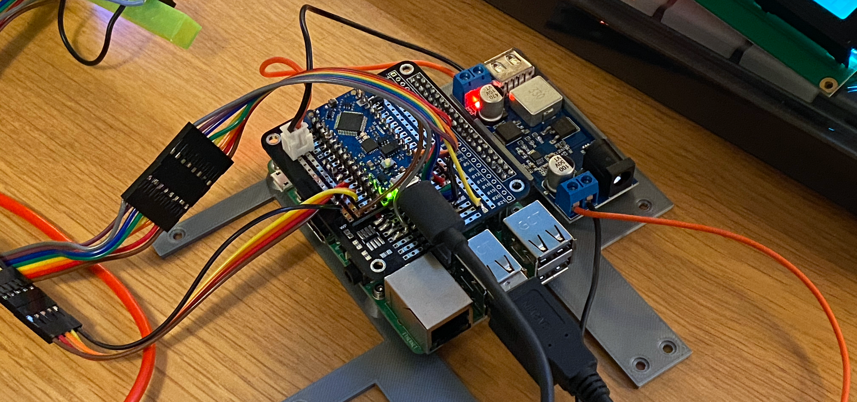
After battling this back and forth for a couple of hours with the only viable solution looking like I would have to write my own library, using an Arduino just seemed… easier. Easily done. Wiring up an Arduino to do encoder interrupt and PWM is basically no lines of code. I played around with using Firmata but as before, the support in Go was lackluster so I defined a simple bi-directional serial protocol that I used to just report buttons and set LED color from Go. Serial support in Go is luckily extremely easy. On top of this the “LCD Backpack” that Adafruit shipped with the LCD had USB so I got a nice USB TTY to write against for the LCD. This made the Go code quite clean.
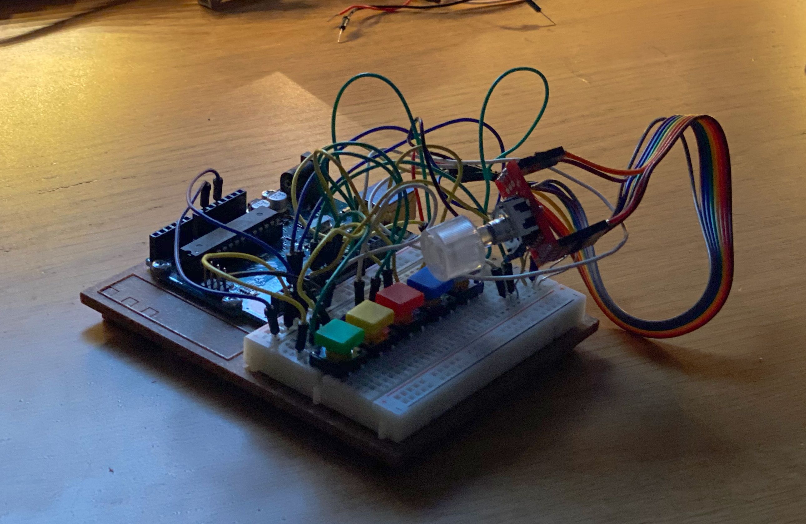
Here it is soldered down on a “hat” for the RPI with the Arduino Nano.
Replicating the audio synthesis
Now the challenge was how to go about generating actual audio. There were a number of options here. The first one was using a hardware MIDI chip such as the VS1053B but after hearing the audio quality I quickly realized that this didn’t sound at all close to what I wanted. Discovering this made it clear that I wanted the sounds of the MT-32/SC-55 but in another package which narrowed the scope to using SoundFonts. SoundFonts was introduced by Creative for their SoundBlaster AWE32 as a way of switching out the sounds on the soundcard, you would load a soundfont onto the device much similar to how you load a text font and the device would use the bank of samples with the surrounding settings to generate audio. Today there’s an array of soundfonts available as the format has taken on a life beyond Creative and there are many MT-32/SC-55 soundfonts available.
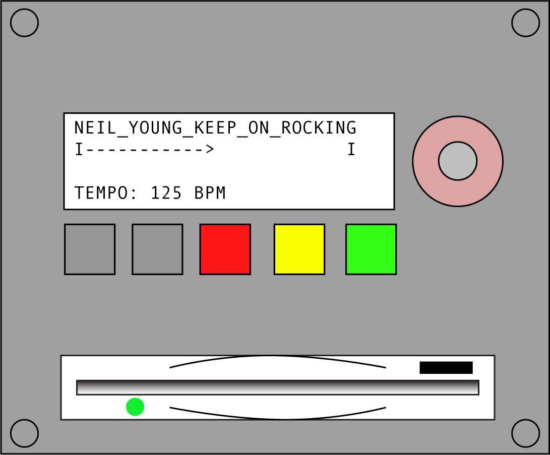
There is a great softsynth that uses soundfonts called FluidSynth. After experimenting with FluidSynth it was clear that the sound generation was spot on, it was able to re-create masterpieces like Neil Young - Rockin’ In The Free World from some jank MIDI file that has the least tight re-creation of this song I’ve ever experienced. To clarify, FluidSynth is fantastic but the MIDI file of this track is really bad, paired with the SC-55 sound it becomes golden. Just listen to this and you will be convinced.
Knowing this the next step was figuring out how to interact with FluidSynth. FluidSynth has a CLI that I could use but it quickly turned out that the CLI was hard to interface against programmatically. FluidSynth also ships with a C API which seemed to be easy enough to interface against. Go has a reasonably easy way of interfacing with C known as cgo. I found some rudimentary bindings on Github that lacked basically all the features I wanted so I forked the repo and started building my own bindings with a more Go-centric API. I added a ton of functionality which is now in my repo called fluidsynth2 on Github for anyone that ever finds themselves wanting to use this from Go.
Writing the controller software
With that issue out the way the remaining part was to write the MT-420 code, which ended up being abstractions for the various hardware devices, a bunch of specific logic around mounting a floppy in Linux year 2020 (harder than you might think) and general state management. The code is absolutely horrible as I wrote most of it before knowing how the hardware actually worked and mocked a lot of it against the terminal, later replacing the modules with actual implementations and discovering peculiarities about how the hardware actually worked that had me refactor code in sad ways. Feels good to see this initialization of the floppy interface though.
///////////////////////////////////////////
// Floppy
///////////////////////////////////////////
delayWriter("Warming up floppy", delay, display)
var storage storage.Storage
if *mockFS {
    storage = mock.New(*mockPath)
} else {
    storage = floppy.New(lconfig.Floppy.Device, lconfig.Floppy.Mountpoint)
}
storage.Init()
The code is structured in two main parts, the first one is to create the “devices” for the “controllers” to use. To easier develop I created “mock” versions of all devices (using Interfaces in Go) which means you can run the entire application in the terminal and use the keyboard to “emulate” the panel. I’m glad I did this as I almost lost my sanity multiple times trying to wrangle with the LCD display. These “devices” are then passed onto the controller which is a state machine pattern that I’ve written a couple of times in Golang at this point. Instead of writing a defined “list” of states I create a interface that the controller host can call on.
type Option interface {
    Run(c *Controller, events <-chan string, end chan bool) string
    Name() string
}
The controller then has an index of all available “modules” and just calls the entrypoint module in the map and calls Run() with the required data. Each module is then responsible for executing the loop and returns a string, which contains the name of the next module. This means that the module can say “go back to X” and the controller will just call that module next loop. This pattern is simple but I’ve found it effective when using “blocking interfaces” such as humans interacting with the device.
The question here though is “Why use Golang?”. To be honest here I think the real reason is that I was lazy and thought that the scope of this was likely to be really small. That turned out to not be the case, especially with all the workarounds I had to do due to pains of interacting with the kernel in Go. Go is really good at solving problems where the hardware is irrelevant and less so dealing with devices like a USB floppy. While I appreciate the fast cross-compilation, approaching this again I would have written this in Rust instead, as the C interop alone would have saved me time on having to work on the FluidSynth bindings. It’s good to do one of these projects though, really pushing the bar of one’s comfort zone language to understand where the weaknesses are.
Demo
You can find all the code for this at my GitHub. The repo also contains the STL files if you want to go ahead and print this yourself.